How To Use A Multimeter On A Car Battery
Updated on: July 15, 2019
Contents
Intro
This guide will certainly reveal you exactly how to utilize a digital multimeter (DMM), a vital tool that you can make use of to diagnose circuits, discover other individuals’s electronic styles, as well as on a car battery. For this reason the ‘multi’-‘meter’ or several measurement name.
One of the most standard things we measure are voltage and also current. A multimeter is likewise wonderful for some basic peace of mind checks and troubleshooting. Is your circuit not working? Does the switch work? Place a meter on it! The multimeter is your very first defence when fixing a system. In this tutorial we will certainly cover measuring voltage, current, resistance and continuity.
Every fixer should understand their method around a multimeter, which has simply north of a zillion utilizes for screening electronic parts and circuits.
In this tutorial we’re going to reveal you just how to use a multimeter. This tutorial is primarily dealt with for beginners that are beginning out in electronic devices and also have no suggestion how to utilize a multimeter and also how it can be beneficial. We’ll check out the most typical functions on a multimeter and exactly how to measure current, voltage, resistance and also exactly how to check continuity.
What is a multimeter and also why do you require one?
A multimeter is a measurement tool definitely required in electronic devices. It integrates 3 important features: a voltmeter, ohmeter, and ammeter, as well as sometimes continuity.
The tool enables you to comprehend what is going on in your circuits. Whenever something in your circuit isn’t functioning, it will certainly help you fixing. Here’s some situations in electronics projects that you’ll locate the multimeter beneficial:
- is the button activate?
- is this cable conducting the electrical power or is it broken?
- how much current is flowing with this led?
- just how much power do you have left on your batteries?
What can multimeters measure?
Almost all multimeters can measure voltage, current, and resistance.
Certain multimeters have a continuity check, resulting in a loud beep if two points are electrically connected. This is handy if, as an example, you are constructing a circuit and connecting cables or soldering; the beep shows every little thing is attached as well as nothing has come loose. You can additionally utilize it to make certain 2 points are not linked, to help stop brief circuits.
A number of multimeters additionally have a diode check function. A diode is like a one-way valve that just allows electrical power circulation in one direction. The precise feature of the diode check can differ from one type to another. If you’re dealing with a diode and can’t inform which method it goes in the circuit, or if you’re uncertain the diode is functioning properly, the check feature can be quite useful. If your DMM has a diode check function, checked out the handbook to figure out precisely how it works.
Advanced models could have various other features, such as the ability to measure and also identify various other electric components, like transistors or capacitors. Considering that not all multimeters have these attributes, we will certainly not cover them in this tutorial. You can read your multimeter’s handbook if you require to use these attributes.
What Do All Of the Symbols Mean?

There’s a lot going on when you look at the selection knob, however if you’re only mosting likely to be doing some fundamental stuff, you will not even utilize half of all the setups. In any case, right here’s a rundown of what each symbol indicates:
Direct Current Voltage (DCV):from time to time it will certainly be denoted with a V– instead. This setup is made use of to measure direct current (DC) voltage crazes like batteries.
Alternating Current Voltage (ACV): Sometimes it will be denoted with a V ~ instead. This setting is used to measure the voltage from alternating current resources, which is rather much anything that links into an outlet, along with the power originating from the electrical outlet itself.
Resistance (Ω): This determines just how much resistance there is in the circuit. The lower the number, the less complicated it is for the current to flow through, and also vice versa.
Continuity: Usually denoted by a wave or diode icon. This merely examines whether a circuit is total by sending a really little amount of current with the circuit and seeing if it makes it out the various other end. Otherwise, then there’s something along the circuit that’s causing a trouble– discover it!
Direct Current Amperage (DCA): Similar to DCV, however as opposed to providing you a voltage analysis, it will tell you the amperage.
Direct Current Gain (hFE): This setting is to test transistors and also their DC gain, yet it’s mostly pointless, given that the majority of electricians as well as enthusiasts will certainly utilize the continuity check rather.
Your multimeter might likewise have a devoted setting for evaluating the amperage of AA, AAA, and 9V batteries. This setting is generally represented with the battery sign.
Once again, you most likely will not even use half of the setups revealed, so do not get overwhelmed if you only understand what a few of them do.
How to Use a Multimeter
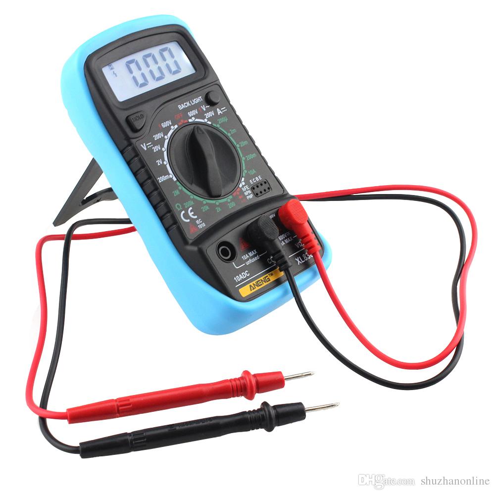
For starters, allow’s look at a few of the various parts of a multimeter. At the extremely standard degree you have the gadget itself, along with two probes, which are the black and also red wires that have plugs on one end and also steel suggestions on the other.
The tool itself has a screen at the top, which offers you your readout, and also there’s a huge selection knob that you can rotate around to choose a certain setup. Each setting may also have different number values, which are there to measure different toughness of voltages, resistances, as well as amps. So if you have your multimeter set to 20 in the DCV area, it will measure voltages up to 20 volts.
Your DMM will certainly additionally feature 2 or 3 ports for plugging in the probes:
- the COM port represent “Common”, and also the black probe will constantly link into this port.
- the VΩmA port (in some cases denoted as mAVΩ) is simply a phrase for voltage, resistance, and also current (in milliamps). This is where the red probe will link into if you’re measuring voltage, resistance, continuity, as well as current less than 200mA.
- the 10ADC port (occasionally represented as simply 10A) is used whenever you’re measuring current that’s greater than 200mA. If you’re uncertain of the current draw, start with this port. On the various other hand, you would certainly not utilize this port in all if you’re measuring anything aside from current.
Caution: Make sure that if you’re measuring anything with a current more than 200mA, you plug the red probe into the 10A port, instead of the 200mA port. Otherwise you might blow the fuse that’s within the multimeter. In addition, measuring anything over 10 amps might blow a fuse or ruin the multimeter as well.
Your measurement tool could have totally separate ports for measuring amps, while the other port is particularly just for voltage, resistance, and continuity, however many more affordable multimeters will share ports.
Anyhow, let’s start really making use of a multimeter. We’ll be measuring the voltage of a AA battery, the current draw of a wall surface clock, as well as the continuity of an easy cord as some instances to get you started as well as familiar with using a multimeter.
Parts of Multimeters
Multimeters have 4 parts:
- Display: this particular is just where the dimensions are displayed
- Selection Knob: this picks what you intend to measure
- Ports: this is where you plug in the probes
- Probes: a multimeter features 2 probes. Usually, one is red and also the various other is black.
Ports
- “COM” or “–” port is where the black probe must be attached. The COM probe is traditionally black.
- 10A is used when measuring big currents, more than 200mA.
- µAmA is used to measure current.
- VΩ enables you to measure voltage and resistance and also examination continuity.
COM
COM represent common and is often attached to Ground or ‘-‘ of a circuit.The COM probe is traditionally black but there is no distinction between the red probe and black probe aside from color.
10A
10A is the special port utilized when measuring large currents (more than 200mA).
Selection Knob
The selection knob permits the customer to set the tool to read different things such as milliamps (mA) of current, voltage (V) and resistance (Ω).
Probes
2 probes are linked into 2 of the ports on the front of the device. The probes have a banana type adapter on the end that connects into the multimeter. Any probe with a banana plug will certainly collaborate with this meter. This permits various types of probes to be made use of.
Probe Types
There are various sorts of probes available. Here are a few of our faves:
- Banana to Alligator Clips: These are great cords for connecting to large wires or pins on a breadboard. Helpful for executing longer term tests where you don’t need to need to hold the probes in area while you adjust a circuit.
- Banana to IC Hook: IC hooks function well on smaller sized ICs and legs of ICs.
- Banana to Tweezers: Tweezers come in handy if you are needing to evaluate SMD elements.
- Banana to Test Probes: If you ever break a probe, they are economical to change!
Measuring Voltage

To begin, let’s measure voltage on a AA battery: Plug the black probe into COM and the red probe right into mAVΩ. Set to “2V” in the DC (straight current) range. Mostly all mobile electronic devices use straight current), not alternating current. Link the black probe to the battery’s ground or ‘-‘ as well as the red probe to power or ‘+’. Squeeze the probes with a little pressure against the favorable as well as adverse terminals of the AA battery. If you’ve got a fresh battery, you must see around 1.5 V on the display (this battery is all new, so its voltage is a little greater than 1.5 V).
You could measure DC voltage or AC voltage. The V with a straight line implies DC voltage. The V with the curly line implies AC voltage.
To measure voltage:
- Set the mode to V with a curly line if you’re measuring AC voltage or to the V with a straight line if you’re measuring DC voltage.
- Make certain the red probe is connected to the port with a V following to it.
- Link the red probe to the favorable side of your component, which is where the current is originating from.
- Connect the COM probe to the opposite side of your component.
- Review the value on the screen.
Pointer: to measure voltage you need to link your multimeter in parallel with the component you desire to measure the voltage. Positioning the multimeter in parallel is positioning each probe along the leads of the component you wish to measure the voltage.
Measuring a battery’s voltage
In this instance we’re going to measure the voltage of a 1.5 V battery. You understand that you’ll have around 1.5 V. So, you ought to select a variety with the selection knob that can read the 1.5 V. So you must pick 2V in the instance of this multimeter. If you take an autorange one, you don’t need to bother with the variety you need to select.
Start by turning on it, plugging the probes right into their respective ports and afterwards establishing the selection knob to the highest possible number value in the DCV area, which in my case is 500 volts. If you do not understand at the very least the voltage series of things you’re measuring, it’s always a great suggestion to start with the highest value first and afterwards work your means down until you get an accurate reading.
In this situation, we understand the AA battery has an extremely low voltage, yet we’ll start at 200 volts simply for the benefit of instance. Next, position the black probe on the unfavorable end of the battery as well as the red probe on the favorable end. Take a look at the reading on the display. Considering that we have the multimeter set to a high 200 volts, it reveals “1.6” on the display, implying 1.6 volts.
Nonetheless, I desire a more exact reading, so I’ll move the selection knob lower down to 20 volts. Below, you can see that we have an even more accurate reading that hovers between 1.60 and 1.61 volts. If you were to ever before set the selection knob to a number worth reduced than the voltage of the important things you’re examining, the multimeter would just read “1”, symbolizing that it’s overloaded. So if I were to set the handle to 200 millivolts (0.2 volts), the 1.6 volts of the AA battery is way too much for the multimeter to handle at that setting.
All the same, you may be asking why you would need to check the voltage of something in the initial area. Well, in this situation with the AA battery, we’re examining to see if it has any kind of juice left. At 1.6 volts, that’s a fully-loaded battery. Nonetheless, if it were to review 1.2 volts, it’s close to being unusable.
In a much more functional situation, you could do this type of measuring on an auto battery to see if it could be passing away or if the alternator (which is what bills the battery) is spoiling. A reading between 12.4-12.7 volts means that the battery remains in good condition. Anything lower as well as that’s proof of a dying battery. Furthermore, start your automobile up as well as rev it up a little bit. If the voltage doesn’t boost to around 14 volts or so, then it’s likely that the alternator is having issues.
Overload
What happens if you pick a voltage setup that is too reduced for the voltage you’re attempting to measure? Absolutely nothing poor. The meter will simply present a 1. This is the meter trying to inform you that it is overloaded or out-of-range. Whatever you’re trying to read is also much for that specific setting. Attempt altering the multimeter handle to a the following highest possible setting.
Selection Knob
As to why does the meter knob read 20V and also not 10V? If you’re wanting to measure a voltage much less than 20V, you rely on the 20V setting. This will certainly enable you to review from 2.00 to 19.99. The very first digit on lots of multimeters is just able to display a ‘1’ so the arrays are restricted to 19.99 rather of 99.99. Hence the 20V max array instead of 99V max array.
Measuring Resistance

Plug the red probe right into the right port and turn the selection knob to the resistance area. Then, connect the probes to the resistor leads. The means you attach the leads does not matter, the outcome is the same.
Normal resistors have shade codes on them. If you don’t understand what they imply, that’s ok! There are a lot of on the internet calculators that are easy to use. Nonetheless, if you ever discover on your own without net accessibility, a multimeter is really convenient at measuring resistance.
Pick an arbitrary resistor as well as established the multimeter to the 20kΩ setting. Then hold the probes versus the resistor legs with the same quantity of stress you when pushing a key on a keyboard.
The meter will read among three points, 0.00, 1, or the real resistor worth.
In this case, the meter checks out 0.97, suggesting this resistor has a worth of 970Ω, or about 1kΩ (remember you remain in the 20kΩ or 20,000 Ohm setting so you require to move the decimal 3 places to the right or 970 Ohms).
If the multimeter reads 1 or presents OL, it’s strained. You will certainly require to try a higher mode such as 200kΩ mode or 2MΩ (megaohm) setting. There is no damage if this happen, it merely suggests the array handle requires to be adjusted.
Should the multimeter checks out 0.00 or almost zero, then you need to reduce the setting to 2kΩ or 200Ω.
Keep in mind that numerous resistors have a 5% tolerance. This implies that the shade codes may indicate 10,000 Ohms (10kΩ), however since of disparities in the production procedure a 10kΩ resistor could be as low as 9.5 kΩ or as high as 10.5 kΩ. Don’t worry, it’ll function just fine as a pull-up or basic resistor.
Generally of thumb, it’s rare to see a resistor less than 1 Ohm. Bear in mind that measuring resistance is not excellent. Temperature can impact the checking out a lot. Additionally, measuring resistance of a device while it is literally installed in a circuit can be really challenging. The surrounding parts on a circuit card can significantly affect the analysis.
The mockup usually appears like with a fundamental clock running of a AA battery. On the silver lining, the wire going from the battery to the clock is damaged up. We just place our two probes in between that break to complete the circuit once again (with the red probe attached to the power resource), just this time our multimeter will review out the amps that the clock is drawing, which in this instance is around 0.08 mA.
While many multimeters can likewise measure alternating current (AC), it’s not truly an excellent idea (specifically if its online power), because AC can be dangerous if you wind up slipping up. If you need to see whether an outlet is working, make use of a non-contact tester instead.
To measure current you need to remember that parts in series share a current. So, you need to attach your multimeter in series with your circuit.
POINTER: to place the multimeter in series, you need to put the red probe on the lead of a component and also the black probe on the next component lead. The multimeter acts as if it was a wire in your circuit. If you disconnect the multimeter, your circuit won’t work.
Before measuring the current, make certain that you’ve connected at a loss probe in the right port, in this situation µAmA. In the example below, the very same circuit of the previous instance is made use of. The multimeter becomes part of the circuit.
Test for Continuity

If there is very reduced resistance between two points, which is much less than a few ohms, the 2 factors are electrically connected as well as you’ll listen to a constant noise. If the noise isn’t continuous or if you don’t hear any type of noise whatsoever, it indicates that what you’re testing has a defective link or isn’t connected in any way.
WARNING: To evaluate continuity you must turn off the system. Shut off the power source!
Touch both probes with each other and also, as they are connected, you’ll hear a constant sound.To test the continuity of a wire, you just need to link each probe to the cable ideas.
Continuity is a terrific method to evaluate if two SMD pins are touching. If your eyes can not see it, the multimeter is generally a great 2nd testing source. When a system is not working, continuity is one more point to aid troubleshoot the system.
- Establish your multimeter to the continuity setting utilizing the selection knob.
- The readout on the display will instantly check out “1”, which implies that there isn’t any type of continuity. This would certainly be appropriate because we have not linked the probes to anything yet.
- Next, make certain the circuit is unplugged and has no power. After that link one probe to one end of the cord and the various other probe to the various other end– it does not matter which probe goes on which end. If there is a full circuit, your multimeter will either beep, show a “0”, or something various other than a “1”. If it still reveals a “1”, after that there’s a trouble and your circuit isn’t full.
- You can also examine that the continuity function functions on your multimeter by touching both probes to each various other. This finishes the circuit as well as your multimeter need to allow you understand that.
A continuity test informs us whether 2 things are electrically connected: if something is continual, an electric current can flow easily from one end to the various other.
If there’s no continuity, it indicates there is a break someplace in the circuit. This can indicate anything from a blown fuse or bad solder joint to an inaccurately wired circuit.
Changing the Fuse
Among the most usual errors with a brand-new multimeter is to measure current on a bread board by probing from VCC to GND. This will instantly short power to ground with the multimeter creating the bread board power supply to brown out. As the current hurries with the multimeter, the inner fuse will warm up and afterwards stress out as 200mA moves via it. It will certainly occur in a flash as well as with no real distinct or physical indication that something is incorrect.
Bear in mind that measuring current is done in series (disrupt the VCC line to the breadboard or microcontroller to measure current). If you attempt to measure the current with a blown fuse, you’ll possibly discover that the meter reads ‘0.00’ and that the system doesn’t switch on like it ought to when you connect the multimeter. This is because the interior fuse is broken as well as acts as a broken cord or open.
To alter the fuse, find your useful dandy mini screw vehicle driver, and also begin obtaining screws. The parts and also PCB traces inside the multimeter are designed to take various amounts of current. You will certainly damage as well as perhaps ruin your multimeter if you accidentally push 5A with the 200mA port.
There are times where you require to measure high current gadgets like a motor or heating component. Do you see both locations to place the red probe on the front of the multimeter? 10A left wing and also mAVΩ on the right? If you attempt to measure greater than 200mA on the mAVΩ port you run the risk of blowing the fuse. However if you make use of the 10A port to measure current, you run a much reduced danger of blowing the fuse. The trade-off is sensitivity. As we chatted about above, by utilizing the 10A port as well as handle setup, you will just have the ability to check out down to 0.01 A or 10mA. A lot of systems use greater than 10mA so the 10A setting and port works well enough. If you’re attempting to measure extremely reduced power (micro or nano amps) the 200mA port with the 2mA, 200uA, or 20uA might be what you require.
Summary
You’re now ready to utilize your digital multimeter to start measuring the globe around you. Do not hesitate to begin using it to address several questions. A digital multimeter will answer several concerns regarding electronic devices.
A multimeter is a necessary tool in any kind of electronics laboratory. In this guide, we’ve shown you How To Use a Multimeter. You’ve learned just how to measure voltage, current as well as resistance, and also how to examine continuity.