How To Use A Multimeter To Measure Voltage
Updated on: July 9, 2019
Contents
The Introduction
These tips and hints will certainly reveal you exactly how to use a digital multimeter (DMM), a crucial tool that you can make use of to identify circuits, learn more about other people’s digital layouts, as well as also to measure voltage. Therefore the ‘multi’-‘meter’ or multiple dimension name.
The most standard things we measure are voltage and also current. A multimeter is also great for some fundamental peace of mind checks and troubleshooting. Is your circuit not working? Does the button work? Place a meter on it! The multimeter is your initial protection when fixing a system. In this tutorial we will certainly cover measuring voltage, current, resistance and also continuity.
Every fixer must understand their means around a multimeter, which has simply north of a zillion utilizes for screening digital parts as well as circuits.
In this tutorial we’re going to reveal you just how to make use of a multimeter. This tutorial is mainly resolved for newbies that are beginning out in electronic devices and have no suggestion just how to make use of a multimeter and just how it can be beneficial. We’ll explore one of the most usual attributes on a multimeter and how to measure current, voltage, resistance and how to examine continuity.
What is a multimeter and also why do you require one?
A multimeter is a measurement tool definitely required in electronics. It incorporates three essential functions: a voltmeter, ohmeter, and ammeter, and in many cases continuity.
The tool allows you to understand what is going on in your circuits. Whenever something in your circuit isn’t functioning, it will aid you fixing. Here’s some circumstances in electronic devices projects that you’ll find the multimeter helpful:
- is the button activate?
- is this cable carrying out the power or is it broken?
- how much current is flowing with this led?
- just how much power do you have left on your batteries?
What can multimeters measure?
Mostly all multimeters can measure voltage, current, and also resistance.
Quite a few multimeters have a continuity check, leading to a loud beep if 2 things are electrically attached. This is practical if, as an example, you are developing a circuit as well as linking cables or soldering; the beep suggests everything is linked as well as nothing has actually come loose. You can also use it to see to it two points are not connected, to assist prevent brief circuits.
A handful of multimeters also have a diode check function. A diode resembles a one-way shutoff that only allows electrical power circulation in one direction. The precise feature of the diode check can vary from one type to another. If you’re collaborating with a diode and can not inform which method it enters the circuit, or if you’re not sure the diode is functioning correctly, the check attribute can be rather useful. If your DMM has a diode check feature, read the guidebook to discover precisely just how it functions.
Advanced models may have other features, such as the capacity to measure and determine other electric parts, like transistors or capacitors. Because not most multimeters have these features, we will not cover them in this tutorial. You can read your multimeter’s manual if you require to utilize these attributes.
What Do All Of the Symbols Mean?
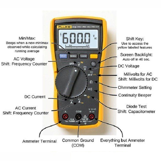
There’s a lot taking place when you take a look at the selection knob, but if you’re just going to be doing some standard stuff, you won’t even utilize half of all the settings. Regardless, right here’s a rundown of what each symbol implies:
Direct Current Voltage (DCV):once in a while it will certainly be represented with a V– instead. This setup is made use of to measure straight current (DC) voltage crazes like batteries.
Alternating Current Voltage (ACV): Sometimes it will be denoted with a V ~ instead. This setting is used to measure the voltage from alternating current sources, which is basically anything that connects right into an electrical outlet, along with the power coming from the electrical outlet itself.
Resistance (Ω): This gauges just how much resistance there is in the circuit. The reduced the number, the much easier it is for the current to flow with, as well as vice versa.
Continuity: Usually signified by a wave or diode symbol. This simply tests whether or not a circuit is complete by sending a very little quantity of current through the circuit and also seeing if it makes it out the other end. Otherwise, then there’s something along the circuit that’s triggering a trouble– discover it!
Direct Current Amperage (DCA): Similar to DCV, however rather than offering you a voltage reading, it will certainly inform you the amperage.
Straight Current Gain (hFE): This setup is to test transistors and their DC gain, yet it’s primarily pointless, considering that most electrical experts as well as enthusiasts will certainly make use of the continuity check rather.
Your multimeter might likewise have a devoted setting for evaluating the amperage of AA, AAA, as well as 9V batteries. This setup is typically denoted with the battery sign.
Again, you probably will not also utilize half of the setups revealed, so don’t obtain overwhelmed if you only understand what a few of them do.
Just how to Use a Multimeter
For starters, allow’s review several of the various parts of a multimeter. At the really basic degree you have the tool itself, in addition to two probes, which are the black and red cable televisions that have plugs on one end and steel ideas on the various other.
The tool itself has a screen on top, which provides you your readout, and there’s a big selection knob that you can rotate around to choose a details setup. Each setting may likewise have different number worths, which exist to measure different strengths of voltages, resistances, and amps. So if you have your multimeter set to 20 in the DCV area, it will measure voltages up to 20 volts.
Your DMM will also feature 2 or 3 ports for connecting in the probes:
- COM port mean “Common”, and the black probe will certainly constantly plug into this port.
- VΩmA port (occasionally signified as mAVΩ) is merely an acronym for voltage, resistance, and also current (in milliamps). This is where the red probe will connect into if you’re measuring voltage, resistance, continuity, and also current less than 200mA.
- the 10ADC port (often represented as simply 10A) is used whenever you’re measuring current that’s more than 200mA. If you’re uncertain of the current draw, begin with this port. On the other hand, you would not use this port at all if you’re measuring anything besides current.
Caution: Make sure that if you’re measuring anything with a current greater than 200mA, you connect the red probe right into the 10A port, instead than the 200mA port. Otherwise you might blow the fuse that’s within of the multimeter. Furthermore, measuring anything over 10 amps might blow a fuse or destroy the multimeter as well.
Your measurement tool may have completely different ports for measuring amps, while the other port is especially just for voltage, resistance, as well as continuity, however a lot of less expensive multimeters will share ports.
Anyhow, let’s begin really utilizing a multimeter. We’ll be measuring the voltage of a AA battery, the current draw of a wall clock, and also the continuity of a straightforward wire as some instances to obtain you began as well as aware of utilizing a multimeter.
Parts of a Multimeter
A multimeter includes 4 components:
- Display: this is where the measurements are presented
- Selection Knob: this picks what you intend to measure
- Ports: this is where you plug in the probes
- Probes: a multimeter features two probes. Generally, one is red and the various other is black.
Ports
- “COM” or “–” port is where the black probe should be connected. The COM probe is conventionally black.
- 10A is made use of when measuring huge currents, higher than 200mA.
- µAmA is made use of to measure current.
- VΩ allows you to measure voltage as well as resistance as well as test continuity.
COM
COM mean typical and is often connected to Ground or ‘-‘ of a circuit.The COM probe is traditionally black however there is no distinction between the red probe as well as black probe aside from color.
10A
10A is the unique port utilized when measuring huge currents (more than 200mA).
Selection Knob
The selection knob allows the individual to establish the tool to read different points such as milliamps (mA) of current, voltage (V) and resistance (Ω).
Probes
2 probes are plugged right into 2 of the ports on the front of the device. The probes have a banana kind port on completion that connects right into the multimeter. Any kind of probe with a banana plug will certainly work with this meter. This enables for various kinds of probes to be made use of.
Probe Types
There are various kinds of probes available. Here are a few of our faves:
- Banana to Alligator Clips: These are wonderful cables for attaching to large wires or pins on a breadboard. Helpful for doing longer term tests where you do not have to have to hold the probes in location while you manipulate a circuit.
- Banana to IC Hook: IC hooks function well on smaller sized ICs and legs of ICs.
- Banana to Tweezers: Tweezers are convenient if you are needing to examine SMD parts.
- Banana to Test Probes: If you ever damage a probe, they are economical to change!
Measuring Voltage

To begin, allow’s measure voltage on a AA battery: Plug the black probe into COM as well as the red probe into mAVΩ. Set to “2V” in the DC (straight current) variety. Nearly all mobile electronic devices utilize straight current), not alternating current. Attach the black probe to the battery’s ground or ‘-‘ and the red probe to power or ‘+’. Press the probes with a little pressure against the positive and adverse terminals of the AA battery. If you’ve obtained a fresh battery, you ought to see around 1.5 V on the display (this battery is all new, so its voltage is somewhat more than 1.5 V).
You can easily measure DC voltage or AC voltage. The V with a straight line suggests DC voltage. The V with the bumpy line suggests AC voltage.
So as to measure voltage understand all of these steps:
- Set the setting to V with a wavy line if you’re measuring AC voltage or to the V with a straight line if you’re measuring DC voltage.
- Make certain the red probe is connected to the port with a V beside it.
- Connect the red probe to the favorable side of your component, which is where the current is coming from.
- Link the COM probe to the opposite side of your component.
- Review the value on the display.
Pointer: to measure voltage you have to attach your multimeter in parallel with the component you want to measure the voltage. Putting the multimeter in parallel is placing each probe along the leads of the component you intend to measure the voltage.
Measuring a battery’s voltage

In this example we’re mosting likely to measure the voltage of a 1.5 V battery. You recognize that you’ll have about 1.5 V. So, you ought to pick an array with the selection knob that can read the 1.5 V. So you must select 2V when it comes to this multimeter. If you get an autorange one, you don’t have to fret about the array you need to choose.
Begin by switching on it, plugging the probes into their respective ports and afterwards establishing the selection knob to the highest number worth in the DCV section, which in my case is 500 volts. If you don’t know a minimum of the voltage series of the important things you’re measuring, it’s constantly a great concept to begin with the highest possible value initially as well as then work your means down till you get a precise analysis.
In this case, we understand the AA battery has an extremely reduced voltage, yet we’ll begin at 200 volts just for the benefit of instance. Next off, position the black probe on the adverse end of the battery and the red probe on the favorable end. Take an appearance at the analysis on the screen. Given that we have the multimeter collection to a high 200 volts, it shows “1.6” on the display, meaning 1.6 volts.
However, I want an even more precise reading, so I’ll move the selection knob lower to 20 volts. Here, you can see that we have a more precise analysis that floats between 1.60 and 1.61 volts. If you were to ever establish the selection knob to a number value less than the voltage of things you’re checking, the multimeter would just check out “1”, symbolizing that it’s strained. So if I were to set the handle to 200 millivolts (0.2 volts), the 1.6 volts of the AA battery is too much for the multimeter to deal with at that setup.
All the same, you may be asking why you would need to examine the voltage of something to begin with. Well, in this case with the AA battery, we’re checking to see if it has any kind of juice left. At 1.6 volts, that’s a fully-loaded battery. Nevertheless, if it were to check out 1.2 volts, it’s close to being unusable.
In a much more functional scenario, you can do this sort of measuring on a car battery to see if it may be passing away or if the alternator (which is what bills the battery) is going poor. A reading between 12.4-12.7 volts means that the battery is in good condition. Anything reduced which’s evidence of a passing away battery. Additionally, begin your car up as well as rev it up a little bit. If the voltage doesn’t boost to about 14 volts or two, then it’s most likely that the generator is having problems.
Overload
What occurs if you select a voltage setup that is also low for the voltage you’re attempting to measure? Nothing poor. The meter will simply show a 1. This is the meter attempting to inform you that it is overloaded or out-of-range. Whatever you’re attempting to check out is as well much for that certain setting. Try altering the multimeter handle to a the next greatest setup.
Selection Knob
Just why does the meter knob reviewed 20V and not 10V? If you’re aiming to measure a voltage much less than 20V, you resort to the 20V setup. This will enable you to check out from 2.00 to 19.99. The initial number on numerous multimeters is only able to present a ‘1’ so the ranges are restricted to 19.99 instead of 99.99. Thus the 20V max variety as opposed to 99V max range.
Measuring Resistance

Plug the red probe right into the right port and turn the selection knob to the resistance section. After that, connect the probes to the resistor leads. The means you link the leads does not matter, the outcome is the very same.
Normal resistors have shade codes on them. If you don’t understand what they suggest, that’s ok! There are lots of online calculators that are very easy to make use of. Nevertheless, if you ever discover yourself without internet access, a multimeter is very helpful at measuring resistance.
Select a random resistor and also established the multimeter to the 20kΩ setup. After that hold the probes versus the resistor legs with the very same quantity of pressure you when pressing a trick on a keyboard.
The meter will review among 3 points, 0.00, 1, or the real resistor value.
In this case, the meter reads 0.97, indicating this resistor has a value of 970Ω, or regarding 1kΩ (remember you are in the 20kΩ or 20,000 Ohm setting so you require to move the decimal 3 areas to the right or 970 Ohms).
If the multimeter checks out 1 or presents OL, it’s overwhelmed. You will require to attempt a greater mode such as 200kΩ mode or 2MΩ (megaohm) mode. There is no damage if this occur, it simply indicates the array handle needs to be readjusted.
In the event that the multimeter reads 0.00 or nearly zero, then you need to reduce the setting to 2kΩ or 200Ω.
Keep in mind that lots of resistors have a 5% tolerance. This suggests that the shade codes might indicate 10,000 Ohms (10kΩ), however as a result of discrepancies in the manufacturing process a 10kΩ resistor can be as low as 9.5 kΩ or as high as 10.5 kΩ. Don’t worry, it’ll work simply fine as a pull-up or basic resistor.
As a policy of thumb, it’s uncommon to see a resistor much less than 1 Ohm. Bear in mind that measuring resistance is not best. Temperature can influence the reading a whole lot. Also, measuring resistance of a device while it is literally mounted in a circuit can be very tricky. The bordering parts on a motherboard can greatly affect the reading.
The mockup generally resembles with a fundamental clock running off of a AA battery. On the silver lining, the cord going from the battery to the clock is separated. We simply put our two probes in between that break to complete the circuit once again (with the red probe connected to the power source), just this time around our multimeter will review out the amps that the clock is pulling, which in this instance is around 0.08 mA.
While the majority of multimeters can additionally measure alternating current (AC), it’s not really an excellent concept (specifically if its online power), considering that AC can be hazardous if you wind up making a mistake. If you require to see whether an outlet is functioning, utilize a non-contact tester instead.
To measure current you require to keep in mind that parts in collection share a current. So, you need to link your multimeter in collection with your circuit.
SUGGESTION: to position the multimeter in collection, you need to position the red probe on the lead of a component and also the black probe on the following component lead. The multimeter acts as if it was a wire in your circuit. If you detach the multimeter, your circuit will not function.
Before measuring the current, make sure that you’ve connected at a loss probe in the appropriate port, in this instance µAmA. In the instance below, the exact same circuit of the previous instance is used. The multimeter is part of the circuit.
Check Continuity

If there is extremely low resistance in between two factors, which is less than a few ohms, the two factors are electrically attached and also you’ll hear a constant noise. If the noise isn’t constant or if you do not hear any noise in any way, it suggests that what you’re testing has a damaged link or isn’t connected whatsoever.
WARNING: In order to check continuity you need to turn off the system. Switch off the power supply.
Touch the 2 probes together and, as they are attached, you’ll hear a continual sound.To test the continuity of a cord, you simply require to attach each probe to the wire suggestions.
Continuity is a terrific method to test if 2 SMD pins are touching. If your eyes can’t see it, the multimeter is normally a terrific 2nd testing source. When a system is not functioning, continuity is another point to assist repair the system.
- Establish your multimeter to the continuity setting utilizing the selection knob.
- The readout on the screen will quickly review “1”, which means that there isn’t any kind of continuity. This would be appropriate because we have not attached the probes to anything yet.
- Next, make certain the circuit is unplugged as well as has no power. Then connect one probe to one end of the wire as well as the other probe to the other end– it does not matter which probe goes on which end. If there is a full circuit, your multimeter will certainly either beep, reveal a “0”, or something other than a “1”. If it still shows a “1”, then there’s a problem and also your circuit isn’t full.
- You can additionally evaluate that the continuity function deals with your multimeter by touching both probes to every other. This completes the circuit and your multimeter need to allow you understand that.
A continuity test informs us whether two things are electrically linked: if something is continuous, an electric current can move freely from one end to the other.
If there’s no continuity, it suggests there is a break somewhere in the circuit. This can indicate anything from a blown fuse or bad solder joint to an improperly wired circuit.
Changing the Fuse
One of the most typical mistakes with a new multimeter is to measure current on a bread board by penetrating from VCC to GND. This will immediately brief power to ground with the multimeter creating the bread board power supply to brownish out. As the current rushes with the multimeter, the internal fuse will certainly warm up as well as after that stress out as 200mA flows via it. It will occur in a fraction of a second as well as without any kind of genuine audible or physical indicator that something is incorrect.
Keep in mind that measuring current is done in series (interrupt the VCC line to the breadboard or microcontroller to measure current). If you try to measure the current with a blown fuse, you’ll possibly see that the meter checks out ‘0.00’ which the system does not switch on like it must when you connect the multimeter. This is due to the fact that the interior fuse is broken and functions as a damaged cable or open.
To alter the fuse, discover your useful dandy mini screw motorist, and begin securing screws. The elements and also PCB traces inside the multimeter are designed to take different amounts of current. You will damage and potentially wreck your multimeter if you accidentally press 5A with the 200mA port.
There are times where you need to measure high current tools like a motor or burner. Do you see the two areas to put the red probe on the front of the multimeter? 10A on the left and mAVΩ on the right? If you attempt to measure even more than 200mA on the mAVΩ port you risk of blowing the fuse. Yet if you utilize the 10A port to measure current, you run a much lower threat of blowing the fuse. The trade-off is level of sensitivity. As we spoke around above, by using the 10A port and also knob setting, you will only be able to review down to 0.01 A or 10mA. The majority of systems make use of more than 10mA so the 10A setup as well as port functions all right. If you’re attempting to measure very reduced power (mini or nano amps) the 200mA port with the 2mA, 200uA, or 20uA can be what you need.
Final thought
You’re now all set to utilize your digital multimeter to begin measuring the globe around you. Do not hesitate to start using it to respond to lots of inquiries. A digital multimeter will answer numerous questions concerning electronic devices.
A multimeter is an important tool in any type of electronics laboratory. In this guide, we’ve shown you How To Use a Multimeter. You’ve learned just how to measure voltage, current as well as resistance, as well as how to examine continuity.