Updated on: December 14, 2018
Contents
Introduction
This article will certainly show you just how to use a digital multimeter (DMM), an important device that you can use to detect circuits, discover concerning other individuals’s digital styles, and also to check for power. For this reason the ‘multi’-‘meter’ or numerous dimension name.
One of the most standard points we measure are voltage as well as current. A multimeter is additionally excellent for some standard sanity checks and also troubleshooting. Is your circuit not functioning? Does the button job? Place a meter on it! The multimeter is your initial protection when troubleshooting a system. In this tutorial we will certainly cover measuring voltage, current, resistance as well as continuity.
Every fixer must know their means around a multimeter, which has just north of a zillion uses for screening electronic parts and also circuits.
In this tutorial we’re mostly likely to show you exactly how to use a multimeter. This tutorial is mainly addressed for beginners who are beginning in electronic devices and have no concept just how to use a multimeter and also exactly how it can be useful. We’ll discover the most common attributes on a multimeter as well as just how to measure current, voltage, resistance and also how to inspect continuity.
What is a multimeter and also why do you need one?
A multimeter is a measurement tool definitely necessary in electronic devices. It incorporates 3 essential functions: a voltmeter, ohmeter, as well as ammeter, as well as sometimes continuity.
The tool allows you to comprehend what is taking place in your circuits. Whenever something in your circuit isn’t functioning, it will aid you fixing. Right here’s some circumstances in electronic devices jobs that you’ll discover the multimeter valuable:
- is the button on?
- is this cable carrying out the electrical power or is it broken?
- just how much current is flowing via this led?
- just how much power do you have left on your batteries?
What will multimeters measure?
Mostly all multimeters can measure voltage, current, and resistance.
A few multimeters have a continuity check, causing a loud beep if 2 points are electrically linked. This is practical if, as an example, you are building a circuit as well as connecting cords or soldering; the beep indicates every little thing is linked and absolutely nothing has come loose. You can additionally utilize it to make certain two things are not connected, to aid prevent brief circuits.
A handful of multimeters additionally have a diode check feature. A diode is like a one-way shutoff that only lets electricity circulation in one instructions. The exact function of the diode check can differ from one type to another. If you’re functioning with a diode and also can’t inform which method it goes in the circuit, or if you’re unsure the diode is working correctly, the check attribute can be quite useful. If your DMM has a diode check function, checked out the handbook to discover precisely just how it works.
Advanced models might have various other features, such as the capability to measure as well as identify various other electrical parts, like transistors or capacitors. Given that not all other multimeters have these features, we will not cover them in this tutorial. You can review your multimeter’s manual if you require to make use of these functions.
What Do Each Of the Symbols Mean?

There’s a lot going on when you take a look at the selection knob, but if you’re only going to be doing some fundamental stuff, you will not also utilize half of all the settings. In any situation, below’s a rundown of what each sign means:
Direct Current Voltage (DCV):every now and then it will certainly be denoted with a V– rather. This setting is used to measure direct current (DC) voltage crazes like batteries.
Alternating Current Voltage (ACV): Sometimes it will be represented with a V ~ rather. This setup is utilized to measure the voltage from alternating current resources, which is quite much anything that connects right into an electrical outlet, along with the power coming from the outlet itself.
Resistance (Ω): This determines just how much resistance there is in the circuit. The lower the number, the much easier it is for the current to stream with, and also vice versa.
Continuity: Usually denoted by a wave or diode icon. This simply evaluates whether a circuit is complete by sending out a really percentage of current through the circuit and also seeing if it makes it out the various other end. If not, after that there’s something along the circuit that’s creating an issue– discover it!
Direct Current Amperage (DCA): Similar to DCV, but rather than offering you a voltage reading, it will certainly inform you the amperage.
Direct Current Gain (hFE): This setting is to evaluate transistors as well as their DC gain, however it’s primarily ineffective, since the majority of electricians and also enthusiasts will certainly use the continuity check rather.
Your multimeter may also have a specialized setup for examining the amperage of AA, AAA, and 9V batteries. This setup is normally signified with the battery symbol.
Again, you most likely will not also use half of the settings revealed, so do not obtain bewildered if you just know what a few of them do.
Exactly how to Use a Multimeter
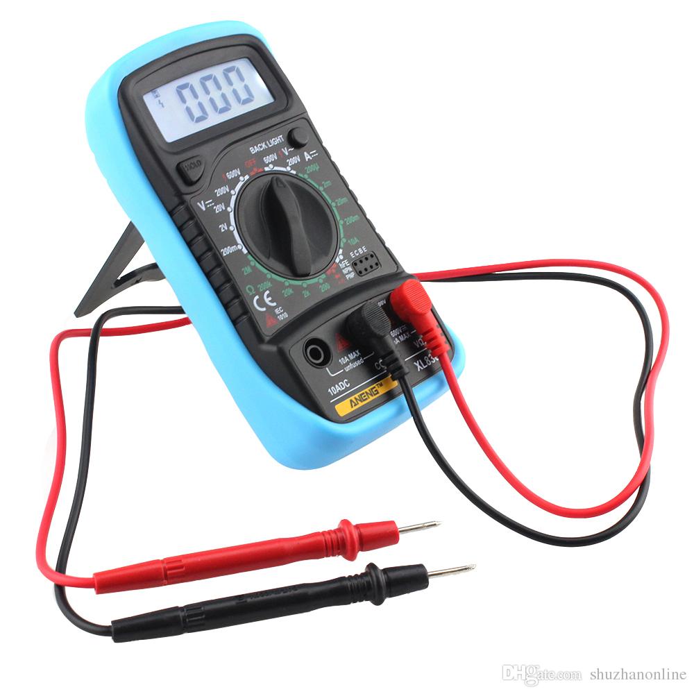
For beginners, let’s review a few of the different parts of a multimeter. At the extremely basic level you have the device itself, along with two probes, which are the black as well as red cables that have plugs on one end as well as metal ideas on the various other.
The tool itself has a screen at the top, which provides you your readout, and also there’s a large selection knob that you can rotate around to pick a certain setting. Each setting may also have various number values, which are there to measure various toughness of voltages, resistances, as well as amps. So if you have your multimeter set to 20 in the DCV area, it will measure voltages approximately 20 volts.
Your DMM will likewise come with two or 3 ports for plugging in the probes:
- COM port represent “Common”, and also the black probe will always plug right into this port.
- VΩmA port (sometimes represented as mAVΩ) is just a phrase for voltage, resistance, and also current (in milliamps). This is where the red probe will plug right into if you’re measuring voltage, resistance, continuity, as well as current less than 200mA.
- the 10ADC port (sometimes denoted as just 10A) is made use of whenever you’re measuring current that’s greater than 200mA. If you’re unsure of the current draw, begin with this port. On the other hand, you would not use this port at all if you’re measuring anything various other than current.
Caution: Make sure that if you’re measuring anything with a current greater than 200mA, you connect the red probe into the 10A port, as opposed to the 200mA port. Or else you can blow the fuse that’s within of the multimeters. Moreover, measuring anything over 10 amps can blow a fuse or damage the multimeter too.
Your measurement tool may have completely separate ports for measuring amps, while the various other port is especially just for voltage, resistance, and also continuity, however most cheaper multimeters will certainly share ports.
Anyhow, let’s begin really using a multimeter. We’ll be measuring the voltage of a AA battery, the current draw of a wall surface clock, as well as the continuity of a simple cord as some instances to get you started and familiar with making use of a multimeter.
Components of Multimeters
Multimeters are made up by 4 important areas:
- Display: this is where the dimensions are displayed
- Selection Knob: this selects what you want to measure
- Ports: this is where you connect in the probes
- Probes: a multimeter features two probes. Usually, one is red and the various other is black.
Ports
- “COM” or “–” port is where the black probe must be linked. The COM probe is conventionally black.
- 10A is used when measuring big currents, better than 200mA.
- µAmA is made use of to measure current.
- VΩ enables you to measure voltage as well as resistance and test continuity.
COM
COM mean usual and also is usually attached to Ground or ‘-‘ of a circuit.The COM probe is traditionally black yet there is no difference in between the red probe and also black probe various other than shade.
10A
10A is the special port utilized when measuring huge currents (higher than 200mA).
Selection Knob
The selection knob allows the individual to establish the tool to review various things such as milliamps (mA) of current, voltage (V) as well as resistance (Ω).
Probes
2 probes are connected into 2 of the ports on the front of the device. The probes have a banana kind port on completion that links into the multimeter. Any type of probe with a banana plug will work with this meter. This permits different types of probes to be used.
Probe Types
There are several kinds of probes available. Here are a few of our faves:
- Banana to Alligator Clips: These are wonderful cords for attaching to large wires or pins on a breadboard. Great for doing longer term examinations where you don’t have to need to hold the probes in position while you manipulate a circuit.
- Banana to IC Hook: IC hooks work well on smaller sized ICs and also legs of ICs.
- Banana to Tweezers: Tweezers are helpful if you are needing to test SMD elements.
- Banana to Test Probes: If you ever break a probe, they are low-cost to change!
Measuring Voltage

To begin, let’s measure voltage on a AA battery: Plug the black probe right into COM and also the red probe into mAVΩ. Establish to “2V” in the DC (direct current) array. Nearly all mobile electronic devices utilize direct current), not alternating current. Attach the black probe to the battery’s ground or ‘-‘ and the red probe to power or ‘+’. Squeeze the probes with a little stress versus the favorable and also unfavorable terminals of the AA battery. If you’ve obtained a fresh battery, you ought to see around 1.5 V on the screen (this battery is all new, so its voltage is slightly greater than 1.5 V).
You can possibly measure DC voltage or AC voltage. The V with a straight line indicates DC voltage. The V with the bumpy line suggests AC voltage.
To measure voltage:
- Set the mode to V with a curly line if you’re measuring AC voltage or to the V with a straight line if you’re measuring DC voltage.
- Ensure the red probe is connected to the port with a V next to it.
- Attach the red probe to the favorable side of your component, which is where the current is coming from.
- Link the COM probe to the opposite of your component.
- Check out the worth on the display.
Tip: to measure voltage you have to connect your multimeter in parallel with the component you wish to measure the voltage. Putting the multimeter in parallel is putting each probe along the leads of the component you desire to measure the voltage.
Measuring a battery’s voltage
In this example we’re going to measure the voltage of a 1.5 V battery. You know that you’ll have approximately 1.5 V. So, you should choose a range with the selection knob that can check out the 1.5 V. So you need to select 2V in the situation of this multimeter. If you get an autorange one, you don’t need to bother with the array you require to choose.
Begin by turning on it, plugging the probes right into their particular ports and afterwards establishing the selection knob to the greatest number worth in the DCV section, which in my situation is 500 volts. If you do not understand at the very least the voltage range of things you’re measuring, it’s constantly a great suggestion to begin with the highest possible value first and after that work your method down up until you get an exact reading.
In this situation, we recognize the AA battery has a really low voltage, yet we’ll begin at 200 volts just for the purpose of instance. Next, put the black probe on the negative end of the battery and also the red probe on the favorable end. Have a look at the reading on the display. Considering that we have the multimeter collection to a high 200 volts, it reveals “1.6” on the display, implying 1.6 volts.
Nevertheless, I desire an even more precise analysis, so I’ll move the selection knob lower down to 20 volts. Below, you can see that we have an even more precise reading that floats between 1.60 and also 1.61 volts. If you were to ever before establish the selection knob to a number worth reduced than the voltage of things you’re testing, the multimeter would certainly just review “1”, symbolizing that it’s overloaded. So if I were to establish the knob to 200 millivolts (0.2 volts), the 1.6 volts of the AA battery is excessive for the multimeter to deal with at that setup.
In any situation, you may be asking why you would certainly need to examine the voltage of something in the very first place. Well, in this situation with the AA battery, we’re inspecting to see if it has any type of juice left. At 1.6 volts, that’s a fully-loaded battery. However, if it were to review 1.2 volts, it’s close to being pointless.
In a more practical situation, you could do this kind of measuring on an auto battery to see if it could be dying or if the alternator (which is what bills the battery) is spoiling. A reading in between 12.4-12.7 volts means that the battery remains in great shape. Anything reduced and also that’s evidence of a dying battery. Furthermore, begin your cars and truck up as well as rev it up a bit. If the voltage does not boost to about 14 volts or so, then it’s likely that the alternator is having problems.
Overload
What takes place if you select a voltage setting that is too low for the voltage you’re trying to measure? Nothing negative. The meter will just present a 1. This is the meter attempting to tell you that it is overloaded or out-of-range. Whatever you’re attempting to review is as well much for that specific setting. Try transforming the multimeter knob to a the next highest setting.
Selection Knob
Exactly why does the meter knob read 20V and not 10V? If you’re aiming to measure a voltage less than 20V, you count on the 20V setup. This will certainly enable you to check out from 2.00 to 19.99. The first digit on numerous multimeters is just able to present a ‘1’ so the arrays are restricted to 19.99 as opposed to 99.99. Therefore the 20V max range rather of 99V max range.
Measuring Resistance

Plug the red probe right into the best port and also turn the selection knob to the resistance section. Then, link the probes to the resistor leads. The means you attach the leads does not matter, the result is the same.
Normal resistors have shade codes on them. If you don’t know what they mean, that’s ok! There are lots of online calculators that are easy to use. However, if you ever discover yourself without web accessibility, a multimeter is extremely helpful at measuring resistance.
Choose an arbitrary resistor and also established the multimeter to the 20kΩ setup. Then hold the probes versus the resistor legs with the same quantity of pressure you when pressing a secret on a keyboard.
The meter will review among three points, 0.00, 1, or the real resistor worth.
In this situation, the meter checks out 0.97, meaning this resistor has a worth of 970Ω, or about 1kΩ (remember you remain in the 20kΩ or 20,000 Ohm setting so you require to move the decimal 3 locations to the right or 970 Ohms).
If the multimeter checks out 1 or displays OL, it’s overwhelmed. You will certainly need to try a greater setting such as 200kΩ setting or 2MΩ (megaohm) mode. There is no damage if this occur, it merely suggests the variety handle needs to be changed.
Whenever the multimeter checks out 0.00 or nearly absolutely no, after that you require to lower the setting to 2kΩ or 200Ω.
Bear in mind that several resistors have a 5% tolerance. This means that the shade codes may show 10,000 Ohms (10kΩ), yet as a result of disparities in the production process a 10kΩ resistor might be as reduced as 9.5 kΩ or as high as 10.5 kΩ. Do not fret, it’ll work just fine as a pull-up or basic resistor.
Generally of thumb, it’s uncommon to see a resistor much less than 1 Ohm. Bear in mind that measuring resistance is not perfect. Temperature level can impact the reviewing a great deal. Also, measuring resistance of a gadget while it is literally set up in a circuit can be extremely challenging. The bordering elements on a motherboard can greatly affect the analysis.
The mockup typically resembles with a fundamental clock escaping of a AA battery. On the positive side, the wire going from the battery to the clock is separated. We merely place our two probes in between that break to complete the circuit once more (with the red probe connected to the source of power), just this moment our multimeter will certainly review out the amps that the clock is pulling, which in this situation is around 0.08 mA.
While a lot of multimeters can likewise measure alternating current (AC), it’s not really a good concept (particularly if its live power), considering that AC can be harmful if you finish up slipping up. If you need to see whether an electrical outlet is working, use a non-contact tester rather.
To measure current you need to remember that elements in collection share a current. So, you need to link your multimeter in collection with your circuit.
SUGGESTION: to place the multimeter in series, you need to place the red probe on the lead of a component and the black probe on the following component lead. The multimeter acts as if it was a wire in your circuit. If you separate the multimeter, your circuit will not work.
Before measuring the current, make sure that you’ve plugged at a loss probe in the best port, in this situation µAmA. In the example below, the exact same circuit of the previous instance is utilized. The multimeter becomes part of the circuit.
Test for Continuity

If there is very reduced resistance in between 2 points, which is much less than a couple of ohms, the 2 factors are electrically attached and you’ll listen to a continual sound. If the audio isn’t continual or if you do not listen to any audio at all, it suggests that what you’re testing has a faulty connection or isn’t connected at all.
WARNING: In order to examine continuity you must shut off the system. Switch off the power source!
Touch the two probes together as well as, as they are linked, you’ll listen to a continual sound.To test the continuity of a cable, you just need to link each probe to the wire tips.
Continuity is a terrific means to check if two SMD pins are touching. If your eyes can not see it, the multimeter is usually a great 2nd testing resource. When a system is not functioning, continuity is another point to assist troubleshoot the system.
- Set your multimeter to the continuity setup using the selection knob.
- The readout on the screen will promptly check out “1”, which suggests that there isn’t any kind of continuity. This would certainly be right since we haven’t attached the probes to anything yet.
- Next off, see to it the circuit is unplugged as well as has no power. Then connect one probe to one end of the wire and also the various other probe to the other end– it does not matter which probe goes on which end. If there is a total circuit, your multimeter will certainly either beep, show a “0”, or something various other than a “1”. If it still shows a “1”, then there’s a trouble and your circuit isn’t total.
- You can also evaluate that the continuity feature works with your multimeter by touching both probes per other. This finishes the circuit as well as your multimeter need to let you know that.
A continuity test informs us whether two points are electrically connected: if something is constant, an electric current can stream easily from one end to the various other.
If there’s no continuity, it suggests there is a break someplace in the circuit. This could indicate anything from a blown fuse or negative solder joint to an incorrectly wired circuit.
Changing the Fuse
Among one of the most usual mistakes with a brand-new multimeter is to measure current on a bread board by penetrating from VCC to GND. This will immediately brief power to ground via the multimeter triggering the bread board power supply to brown out. As the current hurries through the multimeter, the inner fuse will warm up and then wear out as 200mA moves with it. It will certainly take place in a flash as well as with no real audible or physical indicator that something is incorrect.
Bear in mind that measuring current is carried out in collection (interrupt the VCC line to the breadboard or microcontroller to measure current). If you try to measure the current with a blown fuse, you’ll possibly discover that the meter reviews ‘0.00’ and that the system does not switch on like it needs to when you affix the multimeter. This is due to the fact that the interior fuse is damaged and acts as a broken cable or open.
To alter the fuse, locate your helpful dandy mini screw motorist, as well as begin obtaining screws. The parts as well as PCB traces inside the multimeter are created to take different quantities of current. You will certainly harm as well as possibly wreck your multimeter if you inadvertently press 5A through the 200mA port.
There are times where you need to measure high current gadgets like a motor or burner. Do you see both areas to put the red probe on the front of the multimeter? 10A on the left as well as mAVΩ on the right? If you attempt to measure even more than 200mA on the mAVΩ port you run the threat of blowing the fuse. However if you utilize the 10A port to measure current, you run a much reduced threat of blowing the fuse. The trade-off is level of sensitivity. As we spoke about above, by using the 10A port as well as knob setup, you will only be able to read down to 0.01 A or 10mA. The majority of systems utilize greater than 10mA so the 10A setting and port works well enough. If you’re attempting to measure really reduced power (mini or nano amps) the 200mA port with the 2mA, 200uA, or 20uA can be what you require.
Final thought
You’re currently ready to use your digital multimeter to begin measuring the world around you. Do not hesitate to start using it to respond to numerous questions. A digital multimeter will address several inquiries about electronic devices.
A multimeter is a crucial device in any type of electronic devices lab. In this guide, we’ve revealed you How To Use a Multimeter. You’ve discovered how to measure voltage, current and resistance, as well as just how to inspect continuity.