Updated on: December 7, 2018
Contents
The Introduction
This guide will certainly reveal you how to use a digital multimeter (DMM), a vital tool that you can use to identify circuits, find out about various other individuals’s electronic styles, and also also to use a micronta multimeter. Hence the ‘multi’-‘meter’ or several measurement name.
The most fundamental things we measure are voltage and also current. A multimeter is additionally great for some fundamental peace of mind checks as well as troubleshooting. Is your circuit not functioning? Does the switch job? Place a meter on it! The multimeter is your very first defence when fixing a system. In this tutorial we will certainly cover measuring voltage, current, resistance and continuity.
Every fixer ought to recognize their method around a multimeter, which has just north of a zillion uses for screening digital parts and circuits.
In this tutorial we’re mostly likely to show you just how to utilize a multimeter. This tutorial is mainly dealt with for novices that are starting in electronic devices as well as have no idea just how to use a multimeter and also just how it can be valuable. We’ll discover the most usual functions on a multimeter as well as just how to measure current, voltage, resistance as well as exactly how to examine continuity.
What is a multimeter and why do you require one?
A multimeter is a measurement tool absolutely required in electronics. It incorporates 3 necessary functions: a voltmeter, ohmeter, and ammeter, as well as sometimes continuity.
The tool permits you to comprehend what is taking place in your circuits. Whenever something in your circuit isn’t functioning, it will certainly help you repairing. Right here’s some circumstances in electronic devices projects that you’ll locate the multimeter helpful:
- is the switch turn on?
- is this cord conducting the power or is it damaged?
- exactly how much current is flowing with this led?
- just how much power do you have left on your batteries?
What will multimeters measure?
Practically all multimeters can measure voltage, current, and resistance.
Most multimeters have a continuity check, leading to a loud beep if two things are electrically connected. This is helpful if, for example, you are constructing a circuit and also connecting cords or soldering; the beep shows everything is attached as well as nothing has actually come loose. You can additionally use it to ensure two points are not attached, to help avoid brief circuits.
A couple of multimeters likewise have a diode check function. A diode resembles a one-way valve that only lets power circulation in one direction. The exact function of the diode check can vary from one type to another. If you’re dealing with a diode and can not inform which method it goes in the circuit, or if you’re not exactly sure the diode is working appropriately, the check function can be quite useful. If your DMM has a diode check function, checked out the handbook to locate out specifically how it functions.
Advanced models might have other functions, such as the capability to measure and also recognize various other electric components, like transistors or capacitors. Considering that not all of the multimeters have these attributes, we will not cover them in this tutorial. You can review your multimeter’s guidebook if you need to use these functions.
What Do All Of the Symbols Mean?

There’s a whole lot going on when you take a look at the selection knob, however if you’re only going to be doing some basic stuff, you won’t even utilize half of all the settings. In any kind of case, below’s a review of what each symbol means:
Direct Current Voltage (DCV):In some cases it will certainly be represented with a V– instead. This setup is utilized to measure straight current (DC) voltage crazes like batteries.
Alternating Current Voltage (ACV): Sometimes it will certainly be signified with a V ~ instead. This setting is made use of to measure the voltage from alternating current resources, which is virtually anything that connects into an outlet, along with the power originating from the outlet itself.
Resistance (Ω): This determines how much resistance there is in the circuit. The reduced the number, the less complicated it is for the current to move via, and the other way around.
Continuity: Usually signified by a wave or diode icon. This just evaluates whether a circuit is total by sending out a really tiny amount of current through the circuit and seeing if it makes it out the other end. Otherwise, then there’s something along the circuit that’s causing an issue– discover it!
Direct Current Amperage (DCA): Similar to DCV, however instead of offering you a voltage analysis, it will certainly tell you the amperage.
Straight Current Gain (hFE): This setup is to test transistors and also their DC gain, however it’s mostly worthless, because most electrical contractors as well as enthusiasts will make use of the continuity check rather.
Your multimeter might also have a dedicated setting for examining the amperage of AA, AAA, and 9V batteries. This setting is normally signified with the battery symbol.
Once again, you most likely won’t even utilize fifty percent of the setups revealed, so do not get bewildered if you just understand what a few of them do.
Exactly how to Use a Multimeter
For beginners, allow’s look at several of the various components of a multimeter. At the very fundamental degree you have the device itself, along with 2 probes, which are the black as well as red wires that have plugs on one end and also metal tips on the other.
The tool itself has a display screen at the top, which provides you your readout, as well as there’s a big selection knob that you can spin around to pick a details setup. Each setup might additionally have different number worths, which exist to measure various strengths of voltages, resistances, and amps. So if you have your multimeter set to 20 in the DCV area, it will certainly measure voltages up to 20 volts.
Your DMM will also have two or 3 ports for plugging in the probes:
- the COM port represent “Common”, as well as the black probe will certainly constantly connect into this port.
- VΩmA port (in some cases represented as mAVΩ) is just a phrase for voltage, resistance, as well as current (in milliamps). This is where the red probe will connect right into if you’re measuring voltage, resistance, continuity, and also current less than 200mA.
- the 10ADC port (occasionally signified as simply 10A) is made use of whenever you’re measuring current that’s more than 200mA. If you’re unsure of the current draw, begin with this port. On the other hand, you would not utilize this port in all if you’re measuring anything apart from current.
Warning: Make sure that if you’re measuring anything with a current greater than 200mA, you plug the red probe right into the 10A port, rather than the 200mA port. Or else you could blow the fuse that’s within of the multimeter. Furthermore, measuring anything over 10 amps might blow a fuse or ruin the multimeter as well.
Your measurement tool might have completely different ports for measuring amps, while the various other port is particularly simply for voltage, resistance, as well as continuity, however most less expensive multimeters will share ports.
Anyway, allow’s get going in fact utilizing a multimeter. We’ll be measuring the voltage of a AA battery, the current draw of a wall clock, and the continuity of a basic cable as some instances to get you began and also knowledgeable about using a multimeter.
Components of a Multimeter
Multimeters have 4 components:
- Display: this particular is just where the dimensions are presented
- Selection Knob: this chooses what you wish to measure
- Ports: this is where you connect in the probes
- Probes: a multimeter includes two probes. Generally, one is red and the other is black.
Ports
- “COM” or “–” port is where the black probe must be attached. The COM probe is traditionally black.
- 10A is used when measuring large currents, higher than 200mA.
- µAmA is used to measure current.
- VΩ enables you to measure voltage as well as resistance and test continuity.
COM
COM stands for common and also is generally attached to Ground or ‘-‘ of a circuit.The COM probe is traditionally black yet there is no difference in between the red probe and also black probe besides color.
10A
10A is the unique port utilized when measuring huge currents (higher than 200mA).
Selection Knob
The selection knob permits the customer to establish the tool to read various points such as milliamps (mA) of current, voltage (V) and resistance (Ω).
Probes
2 probes are plugged into two of the ports on the front of the device. The probes have a banana type port on the end that links into the multimeter. Any probe with a banana plug will deal with this meter. This permits for various sorts of probes to be utilized.
Probe Types
There are several sorts of probes readily available. Right here are a few of our favorites:
- Banana to Alligator Clips: These are excellent cables for attaching to huge wires or pins on a breadboard. Great for executing longer term tests where you don’t have to need to hold the probes in place while you manipulate a circuit.
- Banana to IC Hook: IC hooks function well on smaller ICs and also legs of ICs.
- Banana to Tweezers: Tweezers are handy if you are needing to examine SMD components.
- Banana to Test Probes: If you ever break a probe, they are inexpensive to change!
Measuring Voltage

To start, let’s measure voltage on a AA battery: Plug the black probe right into COM and also the red probe right into mAVΩ. Establish to “2V” in the DC (straight current) range. Nearly all portable electronics make use of straight current), not alternating current. Link the black probe to the battery’s ground or ‘-‘ as well as the red probe to power or ‘+’. Squeeze the probes with a little stress against the positive as well as adverse terminals of the AA battery. If you’ve obtained a fresh battery, you should see around 1.5 V on the display screen (this battery is brand-new, so its voltage is slightly more than 1.5 V).
You may be able to measure DC voltage or AC voltage. The V with a straight line implies DC voltage. The V with the wavy line indicates AC voltage.
In order to measure voltage follow all these steps:
- Set the mode to V with a wavy line if you’re measuring AC voltage or to the V with a straight line if you’re measuring DC voltage.
- Make sure the red probe is connected to the port with a V beside it.
- Link the red probe to the silver lining of your component, which is where the current is coming from.
- Link the COM probe to the opposite of your component.
- Review the value on the display screen.
Suggestion: to measure voltage you need to attach your multimeter in parallel with the component you intend to measure the voltage. Positioning the multimeter in parallel is placing each probe along the leads of the component you wish to measure the voltage.
Measuring a battery’s voltage
In this instance we’re mosting likely to measure the voltage of a 1.5 V battery. You recognize that you’ll have about 1.5 V. So, you must choose an array with the selection knob that can review the 1.5 V. So you should select 2V when it comes to this multimeter. If you obtain an autorange one, you do not have to stress over the variety you need to pick.
Begin by turning on it, plugging the probes into their particular ports and then setting the selection knob to the highest possible number value in the DCV area, which in my situation is 500 volts. If you do not recognize a minimum of the voltage series of the important things you’re measuring, it’s constantly a great concept to begin with the highest worth first and after that work your way down till you obtain an accurate analysis.
In this case, we know the AA battery has a really reduced voltage, but we’ll start at 200 volts just for the benefit of instance. Next, place the black probe on the adverse end of the battery and also the red probe on the favorable end. Take a look at the analysis on the display. Given that we have the multimeter collection to a high 200 volts, it reveals “1.6” on the display, indicating 1.6 volts.
However, I desire a more exact reading, so I’ll move the selection knob reduced to 20 volts. Right here, you can see that we have an even more precise analysis that floats in between 1.60 and 1.61 volts. If you were to ever set the selection knob to a number value lower than the voltage of the point you’re examining, the multimeter would simply review “1”, indicating that it’s strained. So if I were to set the knob to 200 millivolts (0.2 volts), the 1.6 volts of the AA battery is excessive for the multimeter to deal with at that setup.
Regardless, you could be asking why you would need to check the voltage of something in the very first area. Well, in this instance with the AA battery, we’re inspecting to see if it has any type of juice left. At 1.6 volts, that’s a fully-loaded battery. Nonetheless, if it were to read 1.2 volts, it’s close to being pointless.
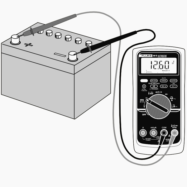
In a more useful scenario, you can do this sort of measuring on a car battery to see if it may be dying or if the alternator (which is what charges the battery) is spoiling. A reading between 12.4-12.7 volts suggests that the battery is in good condition. Anything reduced and also that’s evidence of a passing away battery. In addition, begin your auto up and rev it up a bit. If the voltage doesn’t raise to about 14 volts approximately, then it’s most likely that the generator is having problems.
Overload
What happens if you pick a voltage setup that is too reduced for the voltage you’re attempting to measure? Nothing poor. The meter will simply display a 1. This is the meter trying to inform you that it is overloaded or out-of-range. Whatever you’re trying to review is excessive for that specific setup. Try transforming the multimeter handle to a the following highest setup.
Selection Knob
Exactly why does the meter knob read 20V and not 10V? If you’re seeking to measure a voltage less than 20V, you transform to the 20V setup. This will certainly permit you to review from 2.00 to 19.99. The very first number on numerous multimeters is only able to display a ‘1’ so the arrays are limited to 19.99 as opposed to 99.99. For this reason the 20V max array instead of 99V max range.
Measuring Resistance

Plug the red probe into the ideal port and turn the selection knob to the resistance section. After that, link the probes to the resistor leads. The means you link the leads does not matter, the outcome coincides.
Normal resistors have shade codes on them. If you do not recognize what they imply, that’s ok! There are lots of online calculators that are simple to use. However, if you ever find on your own without web access, a multimeter is very useful at measuring resistance.
Choose out an arbitrary resistor as well as set the multimeter to the 20kΩ setting. After that hold the probes versus the resistor legs with the very same quantity of pressure you when pushing a trick on a keyboard.
The meter will check out one of three things, 0.00, 1, or the real resistor value.
In this case, the meter checks out 0.97, implying this resistor has a worth of 970Ω, or concerning 1kΩ (remember you are in the 20kΩ or 20,000 Ohm mode so you require to move the decimal 3 locations to the right or 970 Ohms).
If the multimeter checks out 1 or displays OL, it’s overloaded. You will certainly need to try a higher mode such as 200kΩ mode or 2MΩ (megaohm) setting. There is no injury if this occur, it merely indicates the variety handle needs to be readjusted.
In the event that the multimeter reads 0.00 or virtually zero, then you require to reduce the setting to 2kΩ or 200Ω.
Keep in mind that numerous resistors have a 5% resistance. This means that the shade codes may show 10,000 Ohms (10kΩ), however since of discrepancies in the manufacturing process a 10kΩ resistor can be as low as 9.5 kΩ or as high as 10.5 kΩ. Do not fret, it’ll work simply fine as a pull-up or general resistor.
As a guideline of thumb, it’s unusual to see a resistor less than 1 Ohm. Keep in mind that measuring resistance is not excellent. Temperature can influence the reviewing a lot. Likewise, measuring resistance of a device while it is literally mounted in a circuit can be really difficult. The bordering components on a circuit board can greatly influence the analysis.
The mockup usually appears like with a basic clock running off of a AA battery. On the silver lining, the cord going from the battery to the clock is separated. We simply position our two probes in between that break to complete the circuit once more (with the red probe attached to the source of power), just this time our multimeter will certainly read out the amps that the clock is drawing, which in this instance is around 0.08 mA.
While most multimeters can also measure alternating current (AC), it’s not actually an excellent concept (specifically if its online power), given that AC can be harmful if you wind up making a blunder. If you need to see whether or not an electrical outlet is functioning, utilize a non-contact tester rather.
To measure current you need to keep in mind that parts in collection share a current. So, you require to link your multimeter in series with your circuit.
TIP: to position the multimeter in series, you need to place the red probe on the lead of a component as well as the black probe on the next component lead. The multimeter acts as if it was a wire in your circuit. If you detach the multimeter, your circuit will not work.
Before measuring the current, make sure that you’ve connected at a loss probe in the ideal port, in this case µAmA. In the example below, the very same circuit of the previous instance is utilized. The multimeter is component of the circuit.
Check for Continuity

If there is really reduced resistance in between two points, which is much less than a couple of ohms, the two points are electrically connected as well as you’ll hear a continual sound. If the audio isn’t continual or if you do not hear any audio whatsoever, it implies that what you’re testing has a damaged link or isn’t linked at all.
WARNING: In order to evaluate continuity you must turn off the system. Turn off the power supply!
Touch both probes together and, as they are connected, you’ll hear a continual sound.To examination the continuity of a cable, you simply require to link each probe to the cord pointers.
Continuity is a terrific means to examine if two SMD pins are touching. If your eyes can’t see it, the multimeter is typically a great 2nd testing source. When a system is not working, continuity is one even more point to assist fix the system.
- Set your multimeter to the continuity setup using the selection knob.
- The readout on the display will quickly review “1”, which implies that there isn’t any kind of continuity. This would be proper because we have not linked the probes to anything yet.
- Next, make certain the circuit is unplugged as well as has no power. After that link one probe to one end of the cord as well as the other probe to the various other end– it does not matter which probe goes on which end. If there is a complete circuit, your multimeter will either beep, reveal a “0”, or something other than a “1”. If it still reveals a “1”, then there’s an issue as well as your circuit isn’t complete.
- You can additionally examine that the continuity feature functions on your multimeter by touching both probes to each various other. This completes the circuit and your multimeter must allow you know that.
A continuity examination informs us whether two things are electrically linked: if something is continual, an electrical current can move easily from one end to the other.
If there’s no continuity, it indicates there is a break somewhere in the circuit. This can indicate anything from a blown fuse or bad solder joint to an inaccurately wired circuit.
Altering the Fuse
Among the most usual mistakes with a new multimeter is to measure current on a bread board by penetrating from VCC to GND. This will promptly brief power to ground with the multimeter triggering the bread board power supply to brown out. As the current hurries via the multimeter, the interior fuse will warm up and after that melt out as 200mA streams via it. It will certainly occur in a flash and also without any real distinct or physical indication that something is wrong.
Bear in mind that measuring current is done in series (interrupt the VCC line to the breadboard or microcontroller to measure current). If you try to measure the current with a blown fuse, you’ll possibly see that the meter reads ‘0.00’ which the system does not transform on like it must when you connect the multimeter. This is due to the fact that the interior fuse is damaged and functions as a busted wire or open.
To change the fuse, locate your useful dandy mini screw chauffeur, and also start securing screws. The components and PCB traces inside the multimeter are created to take different amounts of current. You will certainly damage and also perhaps wreck your multimeter if you accidentally push 5A with the 200mA port.
There are times where you need to measure high current tools like an electric motor or home heating element. Do you see the 2 areas to place the red probe on the front of the multimeter? 10A on the left as well as mAVΩ on the right? If you try to measure greater than 200mA on the mAVΩ port you risk of blowing the fuse. Yet if you make use of the 10A port to measure current, you run a much reduced danger of blowing the fuse. The trade-off is level of sensitivity. As we spoke about above, by utilizing the 10A port and also handle setup, you will only be able to check out down to 0.01 A or 10mA. A lot of systems make use of greater than 10mA so the 10A setup and port works well enough. If you’re attempting to measure extremely reduced power (micro or nano amps) the 200mA port with the 2mA, 200uA, or 20uA could be what you need.
Bottom Line
You’re currently all set to utilize your digital multimeter to start measuring the world around you. Feel free to start using it to answer several inquiries. A digital multimeter will answer many questions concerning electronic devices.
A multimeter is a necessary tool in any kind of electronics lab. In this guide, we’ve revealed you how to use a micronta multimeter. You’ve discovered exactly how to measure voltage, current and resistance, and just how to inspect continuity.