Updated on: December 16, 2018
Contents
The Introduction
These tips and hints will show you just how to use a digital multimeter (DMM), a crucial device that you can utilize to detect circuits, learn more about other individuals’s electronic styles, and also even to check for continuity. Therefore the ‘multi’-‘meter’ or several dimension name.
One of the most standard things we measure are voltage and also current. A multimeter is additionally great for some standard sanity checks as well as troubleshooting. Is your circuit not functioning? Does the button work? Put a meter on it! The multimeter is your very first defence when fixing a system. In this tutorial we will certainly cover measuring voltage, current, resistance and also continuity.
Every fixer must understand their means around a multimeter, which has just north of a zillion uses for testing digital components and circuits.
In this tutorial we’re going to show you how to utilize a multimeter. This tutorial is mostly resolved for novices that are starting in electronics and have no concept how to make use of a multimeter and also how it can be helpful. We’ll check out the most usual features on a multimeter and just how to measure current, voltage, resistance as well as how to examine continuity.
What is a multimeter and also why do you need one?
A multimeter is a measurement tool definitely necessary in electronics. It incorporates 3 essential functions: a voltmeter, ohmeter, as well as ammeter, as well as sometimes continuity.
The tool enables you to understand what is taking place in your circuits. Whenever something in your circuit isn’t working, it will certainly help you fixing. Here’s some situations in electronics projects that you’ll find the multimeter valuable:
- is the button activate?
- is this wire conducting the electrical energy or is it damaged?
- just how much current is streaming with this led?
- just how much power do you have left on your batteries?
What should multimeters measure?
Nearly all multimeters can measure voltage, current, as well as resistance.
Various multimeters have a continuity check, causing a loud beep if 2 points are electrically attached. This is useful if, for circumstances, you are developing a circuit and connecting cables or soldering; the beep shows everything is connected and also absolutely nothing has come loose. You can likewise utilize it to make certain 2 things are not linked, to aid prevent brief circuits.
A lot of multimeters likewise have a diode check feature. A diode resembles a one-way valve that only lets electrical power flow in one direction. The exact function of the diode check can vary from one type to another. If you’re dealing with a diode and also can not inform which way it goes in the circuit, or if you’re not exactly sure the diode is working correctly, the check feature can be rather convenient. If your DMM has a diode check feature, read the manual to find out exactly how it works.
Advanced models might have other features, such as the ability to measure and identify various other electric elements, like transistors or capacitors. Since not all multimeters have these attributes, we will not cover them in this tutorial. You can review your multimeter’s guidebook if you require to use these functions.
What Do Every One Of the Symbols Mean?

There’s a great deal going on when you consider the selection knob, however if you’re only going to be doing some standard stuff, you won’t even make use of half of all the setups. All the same, below’s a rundown of what each sign means:
Direct Current Voltage (DCV):once in a while it will be denoted with a V– rather. This setup is made use of to measure direct current (DC) voltage in points like batteries.
Alternating Current Voltage (ACV): Sometimes it will be denoted with a V ~ rather. This setting is made use of to measure the voltage from alternating current resources, which is practically anything that connects right into an electrical outlet, as well as the power coming from the electrical outlet itself.
Resistance (Ω): This gauges exactly how much resistance there is in the circuit. The lower the number, the much easier it is for the current to move via, and also the other way around.
Continuity: Usually signified by a wave or diode symbol. This simply tests whether a circuit is total by sending a very percentage of current with the circuit and seeing if it makes it out the various other end. Otherwise, then there’s something along the circuit that’s causing a problem– find it!
Direct Current Amperage (DCA): Similar to DCV, but rather of giving you a voltage analysis, it will tell you the amperage.
Straight Current Gain (hFE): This setting is to check transistors as well as their DC gain, however it’s primarily worthless, because many electricians and enthusiasts will make use of the continuity check rather.
Your multimeter may likewise have a committed setting for evaluating the amperage of AA, AAA, and also 9V batteries. This setup is typically signified with the battery sign.
Once again, you possibly will not also use fifty percent of the settings revealed, so don’t obtain bewildered if you only know what a few of them do.
Exactly how to Utilize a Multimeter
For beginners, let’s review several of the different parts of a multimeter. At the really fundamental level you have the device itself, in addition to two probes, which are the black as well as red wires that have plugs on one end as well as steel pointers on the other.
The tool itself has a display on top, which offers you your readout, as well as there’s a large selection knob that you can spin around to select a certain setting. Each setting might additionally have different number values, which are there to measure various staminas of voltages, resistances, as well as amps. So if you have your multimeter set to 20 in the DCV section, it will certainly measure voltages up to 20 volts.
Your DMM will certainly also have 2 or three ports for connecting in the probes:
- the COM port represent “Common”, as well as the black probe will always connect into this port.
- VΩmA port (sometimes signified as mAVΩ) is merely a phrase for voltage, resistance, as well as current (in milliamps). This is where the red probe will link into if you’re measuring voltage, resistance, continuity, and also current less than 200mA.
- the 10ADC port (occasionally signified as just 10A) is used whenever you’re measuring current that’s more than 200mA. If you’re not exactly sure of the current draw, start with this port. On the various other hand, you would not utilize this port in all if you’re measuring anything aside from current.
Warning: Make certain that if you’re measuring anything with a current more than 200mA, you plug the red probe into the 10A port, instead than the 200mA port. Otherwise you could blow the fuse that’s within the multimeter. In addition, measuring anything over 10 amps can blow a fuse or damage the multimeters too.
Your measurement tool could have entirely separate ports for measuring amps, while the other port is particularly simply for voltage, resistance, and also continuity, however most less expensive multimeters will share ports.
Anyhow, allow’s begin in fact utilizing a multimeter. We’ll be measuring the voltage of a AA battery, the current draw of a wall surface clock, and the continuity of an easy wire as some examples to obtain you began and also aware of utilizing a multimeter.
Parts of Multimeters
Multimeters are composed by four essential sections:
- Display: this is where the measurements are displayed
- Selection Knob: this chooses what you wish to measure
- Ports: this is where you plug in the probes
- Probes: a multimeter includes 2 probes. Typically, one is red and the various other is black.
Ports
- “COM” or “–” port is where the black probe must be linked. The COM probe is traditionally black.
- 10A is made use of when measuring big currents, above 200mA.
- µAmA is used to measure current.
- VΩ allows you to measure voltage and resistance and also test continuity.
COM
COM stands for typical and is generally connected to Ground or ‘-‘ of a circuit.The COM probe is conventionally black but there is no difference between the red probe as well as black probe besides color.
10A
10A is the special port used when measuring huge currents (greater than 200mA).
Selection Knob
The selection knob permits the user to set the tool to check out different things such as milliamps (mA) of current, voltage (V) as well as resistance (Ω).
Probes
2 probes are connected right into 2 of the ports on the front of the system. The probes have a banana kind port on the end that plugs into the multimeter. Any probe with a banana plug will deal with this meter. This allows for different types of probes to be used.
Probe Types
There are many various sorts of probes offered. Below are a few of our favorites:
- Banana to Alligator Clips: These are excellent cable televisions for connecting to large cords or pins on a breadboard. Great for carrying out longer term tests where you don’t have to need to hold the probes in place while you manipulate a circuit.
- Banana to IC Hook: IC hooks function well on smaller ICs and legs of ICs.
- Banana to Tweezers: Tweezers come in handy if you are needing to test SMD parts.
- Banana to Test Probes: If you ever before break a probe, they are inexpensive to replace!
Measuring Voltage

To begin, let’s measure voltage on a AA battery: Plug the black probe right into COM as well as the red probe right into mAVΩ. Establish to “2V” in the DC (straight current) array. Mostly all portable electronic devices use direct current), not alternating current. Attach the black probe to the battery’s ground or ‘-‘ and the red probe to power or ‘+’. Squeeze the probes with a little pressure versus the positive and also unfavorable terminals of the AA battery. If you’ve obtained a fresh battery, you must see around 1.5 V on the screen (this battery is new, so its voltage is slightly greater than 1.5 V).
You might measure DC voltage or AC voltage. The V with a straight line indicates DC voltage. The V with the bumpy line implies AC voltage.
To measure voltage:
- Set the mode to V with a wavy line if you’re measuring AC voltage or to the V with a straight line if you’re measuring DC voltage.
- Ensure the red probe is attached to the port with a V alongside it.
- Attach the red probe to the favorable side of your component, which is where the current is coming from.
- Attach the COM probe to the various other side of your component.
- Check out the value on the display.
Suggestion: to measure voltage you have to connect your multimeter in parallel with the component you wish to measure the voltage. Placing the multimeter in parallel is placing each probe along the leads of the component you intend to measure the voltage.
Measuring a battery’s voltage
In this instance we’re going to measure the voltage of a 1.5 V battery. You understand that you’ll have around 1.5 V. So, you must pick a range with the selection knob that can review the 1.5 V. So you must pick 2V when it comes to this multimeter. If you get an autorange one, you do not need to stress over the variety you require to choose.
Begin by switching on it, plugging the probes into their corresponding ports and afterwards setting the selection knob to the highest possible number worth in the DCV section, which in my case is 500 volts. If you do not understand a minimum of the voltage variety of the point you’re measuring, it’s constantly a good suggestion to begin with the greatest value first and then work your means down until you get a precise analysis.
In this instance, we recognize the AA battery has a very low voltage, but we’ll begin at 200 volts simply for the benefit of example. Next, place the black probe on the unfavorable end of the battery and also the red probe on the positive end. Take an appearance at the analysis on the screen. Since we have the multimeter set to a high 200 volts, it shows “1.6” on the display, implying 1.6 volts.
Nonetheless, I want an even more exact analysis, so I’ll move the selection knob reduced down to 20 volts. Right here, you can see that we have an even more exact reading that hovers between 1.60 and also 1.61 volts. If you were to ever set the selection knob to a number value lower than the voltage of things you’re checking, the multimeter would simply read “1”, representing that it’s overwhelmed. So if I were to establish the handle to 200 millivolts (0.2 volts), the 1.6 volts of the AA battery is excessive for the multimeter to handle at that setting.
In any case, you may be asking why you would need to check the voltage of something to begin with. Well, in this instance with the AA battery, we’re inspecting to see if it has any juice left. At 1.6 volts, that’s a fully-loaded battery. However, if it were to read 1.2 volts, it’s close to being pointless.
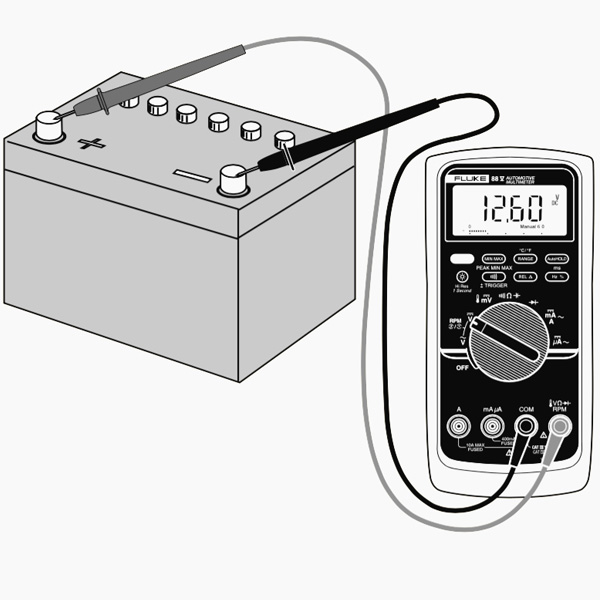
In an extra functional situation, you can do this kind of measuring on a cars and truck battery to see if it may be dying or if the alternator (which is what bills the battery) is spoiling. A reading between 12.4-12.7 volts means that the battery remains in good condition. Anything reduced which’s proof of a dying battery. Furthermore, start your auto up and also rev it up a bit. If the voltage doesn’t boost to about 14 volts or two, then it’s likely that the alternator is having problems.
Overload
What occurs if you choose a voltage setting that is also low for the voltage you’re trying to measure? Absolutely nothing poor. The meter will merely present a 1. This is the meter attempting to tell you that it is overloaded or out-of-range. Whatever you’re trying to read is too much for that particular setting. Try changing the multimeter knob to a the next greatest setup.
Selection Knob
Just why does the meter knob reviewed 20V and also not 10V? If you’re looking to measure a voltage less than 20V, you turn to the 20V setting. This will enable you to read from 2.00 to 19.99. The very first number on lots of multimeters is only able to present a ‘1’ so the arrays are restricted to 19.99 rather than 99.99. Hence the 20V max range as opposed to 99V max range.
Measuring Resistance

Connect the red probe into the appropriate port and also turn the selection knob to the resistance area. After that, connect the probes to the resistor leads. The way you connect the leads doesn’t matter, the result coincides.
Normal resistors have shade codes on them. If you do not understand what they indicate, that’s ok! There are a lot of online calculators that are very easy to utilize. Nevertheless, if you ever before discover yourself without web accessibility, a multimeter is really helpful at measuring resistance.
Pick an arbitrary resistor and also set the multimeter to the 20kΩ setup. Then hold the probes against the resistor legs with the same quantity of pressure you when pressing a key on a key-board.
The meter will check out among three points, 0.00, 1, or the real resistor value.
In this case, the meter reads 0.97, suggesting this resistor has a value of 970Ω, or about 1kΩ (remember you remain in the 20kΩ or 20,000 Ohm mode so you need to move the decimal three places to the right or 970 Ohms).
If the multimeter reads 1 or shows OL, it’s overwhelmed. You will need to attempt a higher setting such as 200kΩ mode or 2MΩ (megaohm) mode. There is no harm if this happen, it merely suggests the variety knob requires to be adjusted.
In the event that the multimeter checks out 0.00 or nearly absolutely no, then you require to decrease the mode to 2kΩ or 200Ω.
Bear in mind that numerous resistors have a 5% tolerance. This implies that the shade codes may show 10,000 Ohms (10kΩ), yet since of discrepancies in the manufacturing process a 10kΩ resistor can be as reduced as 9.5 kΩ or as high as 10.5 kΩ. Do not worry, it’ll function just fine as a pull-up or basic resistor.
As a policy of thumb, it’s unusual to see a resistor much less than 1 Ohm. Bear in mind that measuring resistance is not perfect. Temperature can impact the reviewing a great deal. Also, measuring resistance of a device while it is physically installed in a circuit can be really tricky. The surrounding parts on a circuit board can substantially influence the analysis.
The mockup normally resembles with a fundamental clock running of a AA battery. On the positive side, the wire going from the battery to the clock is separated. We simply place our two probes in between that break to finish the circuit once more (with the red probe connected to the power resource), just this time around our multimeter will read out the amps that the clock is drawing, which in this case is around 0.08 mA.
While the majority of multimeters can likewise measure rotating current (AC), it’s not actually a good concept (especially if its real-time power), considering that AC can be unsafe if you wind up making a mistake. If you need to see whether an outlet is working, utilize a non-contact tester rather.
To measure current you need to birth in mind that components in series share a current. So, you require to link your multimeter in series with your circuit.
IDEA: to put the multimeter in collection, you require to position the red probe on the lead of a component and also the black probe on the next component lead. The multimeter acts as if it was a wire in your circuit. If you separate the multimeter, your circuit won’t function.
Before measuring the current, be sure that you’ve connected at a loss probe in the best port, in this instance µAmA. In the example below, the same circuit of the previous instance is utilized. The multimeter becomes part of the circuit.
Continuity

If there is very low resistance between 2 points, which is less than a couple of ohms, the two points are electrically attached and also you’ll hear a continual sound. If the sound isn’t constant or if you don’t hear any audio whatsoever, it indicates that what you’re testing has a damaged connection or isn’t linked in all.
WARNING: In order to examine continuity you need to turn off the system! Turn off the power supply.
Touch both probes with each other and also, as they are attached, you’ll hear a continuous sound.To test the continuity of a cord, you just need to link each probe to the cord pointers.
Continuity is an excellent method to evaluate if 2 SMD pins are touching. If your eyes can not see it, the multimeter is normally a wonderful 2nd testing source. When a system is not functioning, continuity is one more point to assist troubleshoot the system.
- Establish your multimeter to the continuity setup using the selection knob.
- The readout on the screen will quickly review “1”, which suggests that there isn’t any kind of continuity. This would be appropriate given that we haven’t connected the probes to anything yet.
- Next, ensure the circuit is unplugged as well as has no power. Then attach one probe to one end of the wire as well as the various other probe to the other end– no matter which probe takes place which end. If there is a full circuit, your multimeter will either beep, reveal a “0”, or something besides a “1”. If it still shows a “1”, after that there’s a problem and also your circuit isn’t complete.
- You can also test that the continuity function works with your multimeter by touching both probes per other. This completes the circuit and also your multimeter ought to allow you understand that.
A continuity test informs us whether 2 points are electrically attached: if something is continuous, an electrical current can flow easily from one end to the various other.
If there’s no continuity, it indicates there is a break someplace in the circuit. This can suggest anything from a blown fuse or bad solder joint to an inaccurately wired circuit.
Changing the Fuse
One of the most usual mistakes with a new multimeter is to measure current on a bread board by probing from VCC to GND. This will instantly short power to ground with the multimeter causing the bread board power supply to brownish out. As the current rushes through the multimeter, the internal fuse will warm up and afterwards stress out as 200mA moves with it. It will certainly occur in a flash as well as without any actual audible or physical indication that something is incorrect.
Remember that measuring current is done in series (disrupt the VCC line to the breadboard or microcontroller to measure current). If you try to measure the current with a blown fuse, you’ll possibly discover that the meter reviews ‘0.00’ which the system doesn’t transform on like it needs to when you connect the multimeter. This is due to the fact that the inner fuse is damaged and also works as a damaged wire or open.
To change the fuse, discover your convenient dandy mini screw vehicle driver, as well as start taking out screws. The parts and PCB traces inside the multimeter are designed to take various amounts of current. You will certainly damage as well as potentially spoil your multimeter if you inadvertently push 5A through the 200mA port.
There are times where you need to measure high current devices like a motor or burner. Do you see both areas to place the red probe on the front of the multimeter? 10A on the left and also mAVΩ on the right? If you attempt to measure greater than 200mA on the mAVΩ port you run the risk of blowing the fuse. However if you use the 10A port to measure current, you run a much lower threat of blowing the fuse. The trade-off is level of sensitivity. As we talked about above, by using the 10A port as well as knob setting, you will only have the ability to check out to 0.01 A or 10mA. Most of systems utilize greater than 10mA so the 10A setting as well as port works all right. If you’re attempting to measure extremely low power (micro or nano amps) the 200mA port with the 2mA, 200uA, or 20uA might be what you need.
Final thought
You’re currently ready to use your digital multimeter to start measuring the world around you. Do not hesitate to begin using it to respond to lots of questions. A digital multimeter will respond to several concerns concerning electronic devices.
A multimeter is a necessary tool in any kind of electronics laboratory. In this guide, we’ve revealed you How To Use a Multimeter. You’ve learned exactly how to measure voltage, current and also resistance, and also how to check continuity.