Updated on: December 17, 2018
Contents
The Introduction
This tutorial will show you just how to make use of a digital multimeter (DMM), a vital tool that you can utilize to diagnose circuits, learn more about various other individuals’s electronic layouts, and also even test car lights. Thus the ‘multi’-‘meter’ or numerous measurement name.
One of the most basic things we measure are voltage and current. A multimeter is also excellent for some fundamental peace of mind checks and troubleshooting. Is your circuit not functioning? Does the button work? Place a meter on it! The multimeter is your very first protection when troubleshooting a system. In this tutorial we will cover measuring voltage, current, resistance and also continuity.
Every fixer needs to know their means around a multimeter, which has just north of a zillion utilizes for screening electronic parts and also circuits.
In this tutorial we’re going to reveal you exactly how to make use of a multimeter. This tutorial is primarily resolved for beginners that are starting in electronics and have no concept exactly how to utilize a multimeter and also how it can be valuable. We’ll explore the most usual features on a multimeter and also just how to measure current, voltage, resistance and just how to examine continuity.
What is a multimeter and why do you need one?
A multimeter is a measurement device definitely necessary in electronic devices. It incorporates 3 crucial attributes: a voltmeter, ohmeter, and also ammeter, and in many cases continuity.
The tool enables you to understand what is going on in your circuits. Whenever something in your circuit isn’t functioning, it will certainly help you fixing. Right here’s some circumstances in electronics tasks that you’ll locate the multimeter beneficial:
- is the button activate?
- is this wire carrying out the electrical energy or is it broken?
- how much current is moving via this led?
- how much power do you have left on your batteries?
What should multimeters measure?
Mostly all multimeters can measure voltage, current, and also resistance.
Some multimeters have a continuity check, leading to a loud beep if 2 points are electrically linked. This is valuable if, as an example, you are developing a circuit as well as linking cables or soldering; the beep shows every little thing is linked and also nothing has actually come loose. You can additionally utilize it to ensure two points are not linked, to aid stop short circuits.
A lot of multimeters likewise have a diode check function. A diode is like a one-way shutoff that just lets power flow in one direction. The exact function of the diode check can differ from one type to another. If you’re working with a diode and can not inform which way it enters the circuit, or if you’re unsure the diode is functioning appropriately, the check attribute can be quite convenient. If your DMM has a diode check feature, checked out the guidebook to learn specifically just how it functions.
Advanced models might have various other functions, such as the capacity to measure and determine various other electric components, like transistors or capacitors. Given that not nearly all multimeters have these attributes, we will certainly not cover them in this tutorial. You can read your multimeter’s manual if you need to make use of these functions.
What Do Every One Of the Symbols Mean?
There’s a lot going on when you check out the selection knob, however if you’re just going to be doing some basic things, you won’t also use half of all the settings. Regardless, here’s a review of what each icon suggests:
Direct Current Voltage (DCV):once in a while it will certainly be signified with a V– instead. This setting is utilized to measure direct current (DC) voltage crazes like batteries.
Alternating Current Voltage (ACV): Sometimes it will be represented with a V ~ instead. This setting is made use of to measure the voltage from alternating current sources, which is rather much anything that plugs right into an outlet, in addition to the power coming from the electrical outlet itself.
Resistance (Ω): This gauges how much resistance there remains in the circuit. The reduced the number, the less complicated it is for the current to stream with, and also vice versa.
Continuity: Usually signified by a wave or diode sign. This merely tests whether or not a circuit is complete by sending an extremely percentage of current through the circuit and seeing if it makes it out the other end. If not, after that there’s something along the circuit that’s creating an issue– discover it!
Straight Current Amperage (DCA): Similar to DCV, however rather than offering you a voltage analysis, it will tell you the amperage.
Straight Current Gain (hFE): This setup is to check transistors and also their DC gain, however it’s mostly useless, since the majority of electrical experts and also hobbyists will certainly make use of the continuity check rather.
Your multimeter might also have a committed setup for testing the amperage of AA, AAA, and also 9V batteries. This setting is usually denoted with the battery icon.
Once more, you possibly won’t even make use of fifty percent of the setups shown, so do not get bewildered if you only know what a few of them do.
How to Utilize a Multimeter
For starters, let’s review several of the various parts of a multimeter. At the really basic degree you have the device itself, together with 2 probes, which are the black and also red cables that have plugs on one end as well as metal ideas on the various other.
The tool itself has a display on top, which provides you your readout, and also there’s a big selection knob that you can spin around to pick a particular setting. Each setup may also have various number worths, which exist to measure various strengths of voltages, resistances, as well as amps. So if you have your multimeter collection to 20 in the DCV section, it will measure voltages as much as 20 volts.
Your DMM will certainly additionally come with 2 or three ports for plugging in the probes:
- COM port represent “Common”, as well as the black probe will always connect into this port.
- the VΩmA port (sometimes denoted as mAVΩ) is just an acronym for voltage, resistance, as well as current (in milliamps). This is where the red probe will connect into if you’re measuring voltage, resistance, continuity, as well as current much less than 200mA.
- the 10ADC port (sometimes represented as just 10A) is made use of whenever you’re measuring current that’s even more than 200mA. If you’re not exactly sure of the current draw, start with this port. On the various other hand, you would not use this port in any way if you’re measuring anything besides current.
Warning: Make sure that if you’re measuring anything with a current greater than 200mA, you connect the red probe right into the 10A port, instead of the 200mA port. Otherwise you might blow the fuse that’s inside of the multimeters. Furthermore, measuring anything over 10 amps might blow a fuse or destroy the multimeters as well.
Your measurement tool may have entirely different ports for measuring amps, while the various other port is especially just for voltage, resistance, and also continuity, but many cheaper multimeters will certainly share ports.
Anyhow, allow’s obtain started in fact using a multimeter. We’ll be measuring the voltage of a AA battery, the current draw of a wall clock, and also the continuity of a basic wire as some instances to obtain you started as well as familiar with making use of a multimeter.
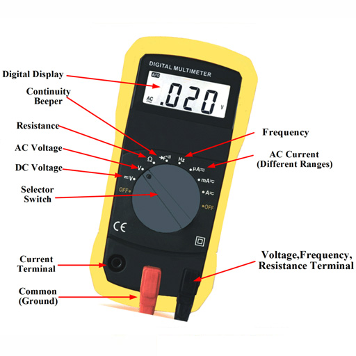
Components of a Multimeter
Multimeters are composed by 4 vital sections:
- Display: this particular is where the measurements are shown
- Selection Knob: this chooses what you intend to measure
- Ports: this is where you connect in the probes
- Probes: a multimeter includes two probes. Typically, one is red and the other is black.
Ports
- “COM” or “–” port is where the black probe ought to be linked. The COM probe is conventionally black.
- 10A is utilized when measuring huge currents, higher than 200mA.
- µAmA is made use of to measure current.
- VΩ enables you to measure voltage and also resistance and also examination continuity.
COM
COM stands for usual as well as is often attached to Ground or ‘-‘ of a circuit.The COM probe is conventionally black but there is no difference in between the red probe and black probe aside from shade.
10A
10A is the special port used when measuring big currents (higher than 200mA).
Selection Knob
The selection knob allows the user to establish the tool to check out various things such as milliamps (mA) of current, voltage (V) and also resistance (Ω).
Probes
Two probes are connected right into 2 of the ports on the front of the system. The probes have a banana kind port on completion that links into the multimeter. Any kind of probe with a banana plug will certainly work with this meter. This permits different types of probes to be used.
Probe Types
There are several various kinds of probes offered. Below are a few of our favorites:
- Banana to Alligator Clips: These are wonderful wires for linking to big cables or pins on a breadboard. Great for executing longer term tests where you don’t have to have to hold the probes in place while you control a circuit.
- Banana to IC Hook: IC hooks function well on smaller sized ICs as well as legs of ICs.
- Banana to Tweezers: Tweezers are convenient if you are needing to examine SMD components.
- Banana to Test Probes: If you ever before damage a probe, they are cheap to change!
Measuring Voltage

To start, let’s measure voltage on a AA battery: Plug the black probe into COM and the red probe right into mAVΩ. Establish to “2V” in the DC (direct current) array. Almost all portable electronic devices use direct current), not alternating current. Link the black probe to the battery’s ground or ‘-‘ and also the red probe to power or ‘+’. Squeeze the probes with a little pressure against the favorable and unfavorable terminals of the AA battery. If you’ve obtained a fresh battery, you ought to see around 1.5 V on the display screen (this battery is all new, so its voltage is somewhat greater than 1.5 V).
You may measure DC voltage or AC voltage. The V with a straight line indicates DC voltage. The V with the curly line suggests AC voltage.
Measuring voltage
- Set the setting to V with a curly line if you’re measuring AC voltage or to the V with a straight line if you’re measuring DC voltage.
- Ensure the red probe is linked to the port with a V next to it.
- Connect the red probe to the silver lining of your component, which is where the current is coming from.
- Link the COM probe to the opposite of your component.
- Read the worth on the display.
Idea: to measure voltage you need to attach your multimeter in parallel with the component you desire to measure the voltage. Positioning the multimeter in parallel is putting each probe along the leads of the component you want to measure the voltage.
Measuring a battery’s voltage

In this instance we’re going to measure the voltage of a 1.5 V battery. You know that you’ll have around 1.5 V. So, you must select a variety with the selection knob that can review the 1.5 V. So you ought to select 2V when it comes to this multimeter. If you get an autorange one, you don’t need to stress over the range you require to choose.
Start by activating it, connecting the probes into their respective ports and also then establishing the selection knob to the highest number value in the DCV section, which in my instance is 500 volts. If you don’t recognize at the very least the voltage array of things you’re measuring, it’s constantly an excellent concept to begin with the greatest worth initially and after that work your means down up until you get a precise reading.
In this situation, we understand the AA battery has an extremely reduced voltage, yet we’ll begin at 200 volts just for the benefit of instance. Next off, put the black probe on the adverse end of the battery and also the red probe on the favorable end. Have a look at the analysis on the display. Because we have the multimeter collection to a high 200 volts, it shows “1.6” on the screen, implying 1.6 volts.
Nevertheless, I want a more precise analysis, so I’ll move the selection knob lower to 20 volts. Right here, you can see that we have a more precise analysis that floats between 1.60 and also 1.61 volts. If you were to ever before establish the selection knob to a number value less than the voltage of the thing you’re examining, the multimeter would simply review “1”, indicating that it’s overwhelmed. So if I were to establish the knob to 200 millivolts (0.2 volts), the 1.6 volts of the AA battery is also much for the multimeter to deal with at that setup.
Regardless, you may be asking why you would certainly require to test the voltage of something in the initial area. Well, in this case with the AA battery, we’re checking to see if it has any type of juice left. At 1.6 volts, that’s a fully-loaded battery. Nonetheless, if it were to review 1.2 volts, it’s close to being pointless.
In a more functional situation, you could do this type of measuring on a cars and truck battery to see if it could be dying or if the generator (which is what bills the battery) is going poor. A reading between 12.4-12.7 volts suggests that the battery is in good condition. Anything reduced and also that’s proof of a dying battery. Furthermore, start your vehicle up as well as rev it up a bit. If the voltage does not raise to around 14 volts or two, after that it’s likely that the alternator is having problems.
Overload
What occurs if you pick a voltage setting that is too low for the voltage you’re trying to measure? Nothing poor. The meter will just display a 1. This is the meter trying to tell you that it is overloaded or out-of-range. Whatever you’re trying to check out is as well much for that specific setup. Try altering the multimeter knob to a the following highest possible setup.
Selection Knob
For what reason does the meter knob checked out 20V and also not 10V? If you’re looking to measure a voltage less than 20V, you rely on the 20V setup. This will permit you to review from 2.00 to 19.99. The first digit on lots of multimeters is only able to present a ‘1’ so the varieties are restricted to 19.99 as opposed to 99.99. Hence the 20V max array instead of 99V max range.
Measuring Resistance

Plug the red probe into the right port and turn the selection knob to the resistance section. Then, link the probes to the resistor leads. The way you attach the leads doesn’t matter, the outcome is the same.
Normal resistors have color codes on them. If you do not know what they imply, that’s ok! There are plenty of on-line calculators that are easy to make use of. Nonetheless, if you ever find on your own without internet access, a multimeter is very useful at measuring resistance.
Select an arbitrary resistor and also established the multimeter to the 20kΩ setup. Then hold the probes versus the resistor legs with the same quantity of pressure you when pressing a secret on a keyboard.
The meter will certainly check out one of three things, 0.00, 1, or the real resistor worth.
In this instance, the meter reads 0.97, meaning this resistor has a worth of 970Ω, or regarding 1kΩ (remember you are in the 20kΩ or 20,000 Ohm setting so you require to move the decimal three locations to the right or 970 Ohms).
If the multimeter reads 1 or shows OL, it’s overwhelmed. You will need to try a greater setting such as 200kΩ setting or 2MΩ (megaohm) setting. There is no harm if this occur, it just means the range handle requires to be changed.
Whenever the multimeter reviews 0.00 or nearly no, then you need to lower the setting to 2kΩ or 200Ω.
Keep in mind that lots of resistors have a 5% tolerance. This suggests that the shade codes may show 10,000 Ohms (10kΩ), but due to discrepancies in the manufacturing procedure a 10kΩ resistor can be as low as 9.5 kΩ or as high as 10.5 kΩ. Do not fret, it’ll function simply great as a pull-up or basic resistor.
As a rule of thumb, it’s unusual to see a resistor less than 1 Ohm. Keep in mind that measuring resistance is not ideal. Temperature level can affect the checking out a lot. Additionally, measuring resistance of a gadget while it is physically installed in a circuit can be extremely difficult. The surrounding elements on a motherboard can greatly influence the reading.
The mockup typically looks like with a fundamental clock escaping of a AA battery. On the silver lining, the cord going from the battery to the clock is separated. We simply place our two probes in between that break to complete the circuit once more (with the red probe linked to the source of power), just this time around our multimeter will read out the amps that the clock is drawing, which in this situation is around 0.08 mA.
While many multimeters can likewise measure rotating current (AC), it’s not truly an excellent concept (especially if its real-time power), considering that AC can be dangerous if you end up making a mistake. If you require to see whether or not an outlet is working, make use of a non-contact tester rather.
To measure current you require to bear in mind that parts in collection share a current. So, you need to connect your multimeter in collection with your circuit.
SUGGESTION: to position the multimeter in collection, you require to put the red probe on the lead of a component as well as the black probe on the next component lead. The multimeter acts as if it was a cable in your circuit. If you disconnect the multimeter, your circuit won’t work.
Before measuring the current, be certain that you’ve plugged at a loss probe in the right port, in this instance µAmA. In the example listed below, the same circuit of the previous example is used. The multimeter is part of the circuit.
Test Continuity

If there is very low resistance between 2 points, which is less than a few ohms, both points are electrically connected as well as you’ll listen to a continuous sound. If the sound isn’t continuous or if you don’t listen to any kind of noise in all, it means that what you’re testing has a damaged link or isn’t connected whatsoever.
CAUTION: To evaluate continuity you need to shut off the system! Shut off the power source!
Touch the two probes with each other and also, as they are linked, you’ll hear a constant sound.To examination the continuity of a cord, you just require to link each probe to the wire pointers.
Continuity is a fantastic way to check if two SMD pins are touching. If your eyes can’t see it, the multimeter is usually a great second testing resource. When a system is not working, continuity is one even more point to assist fix the system.
- Establish your multimeter to the continuity setup using the selection knob.
- The readout on the screen will instantaneously read “1”, which suggests that there isn’t any continuity. This would be appropriate since we have not linked the probes to anything yet.
- Next off, make certain the circuit is unplugged and has no power. After that connect one probe to one end of the wire and also the other probe to the various other end– no matter which probe goes on which end. If there is a full circuit, your multimeter will certainly either beep, reveal a “0”, or something various other than a “1”. If it still reveals a “1”, after that there’s a problem as well as your circuit isn’t total.
- You can likewise test that the continuity feature deals with your multimeter by touching both probes per various other. This finishes the circuit as well as your multimeter must allow you understand that.
A continuity examination informs us whether 2 points are electrically linked: if something is constant, an electrical current can stream openly from one end to the various other.
If there’s no continuity, it implies there is a break someplace in the circuit. This might show anything from a blown fuse or negative solder joint to an incorrectly wired circuit.
Changing the Fuse
One of one of the most typical errors with a brand-new multimeter is to measure current on a bread board by probing from VCC to GND. This will quickly brief power to ground with the multimeter creating the bread board power supply to brown out. As the current hurries with the multimeter, the inner fuse will warm up and after that stress out as 200mA streams with it. It will take place in a fraction of a second and also without any actual audible or physical indicator that something is wrong.
Bear in mind that measuring current is done in series (disrupt the VCC line to the breadboard or microcontroller to measure current). If you attempt to measure the current with a blown fuse, you’ll possibly see that the meter reviews ‘0.00’ which the system doesn’t turn on like it needs to when you attach the multimeter. This is due to the fact that the inner fuse is damaged and also functions as a broken wire or open.
To change the fuse, find your useful dandy mini screw chauffeur, and also start taking out screws. The components and PCB traces inside the multimeter are made to take different amounts of current. You will damage and also potentially destroy your multimeter if you inadvertently press 5A with the 200mA port.
There are times where you require to measure high current devices like a motor or burner. Do you see the two places to place the red probe on the front of the multimeter? 10A left wing and also mAVΩ on the right? If you attempt to measure greater than 200mA on the mAVΩ port you run the risk of blowing the fuse. However if you use the 10A port to measure current, you run a much lower danger of blowing the fuse. The compromise is level of sensitivity. As we spoke around above, by utilizing the 10A port and knob setting, you will only have the ability to check out down to 0.01 A or 10mA. A lot of systems make use of greater than 10mA so the 10A setting and also port functions well enough. If you’re attempting to measure extremely low power (mini or nano amps) the 200mA port with the 2mA, 200uA, or 20uA can be what you need.
Final thought
You’re now ready to use your digital multimeter to begin measuring the world around you. Feel totally free to start using it to address numerous inquiries. A digital multimeter will certainly answer several concerns regarding electronics.
A multimeter is a vital tool in any kind of electronic devices laboratory. In this guide, we’ve shown you How To Use a Multimeter. You’ve found out exactly how to measure voltage, current as well as resistance, and also how to check continuity.